
Speed-Controlled RGB Strobe: TME EDU ARD 2 & Arduino Uno R4 WiFi
One of the most satisfying beginner-to-intermediate microcontroller projects is controlling addressable RGB LEDs with analog inputs. Physical dial turns can be converted into real-time lighting effects by combining an analog potentiometer with a strip or array of WS2812B NeoPixels.
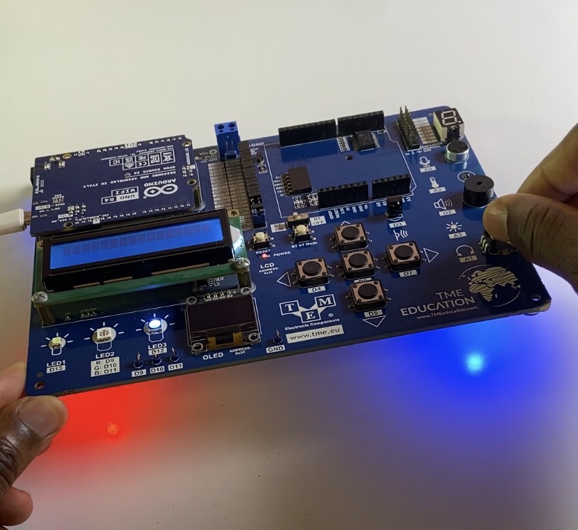
In this guide, we will build an alternating red-and-blue strobe effect on the TME EDU ARD 2 evaluation board powered by the Arduino Uno R4 WiFi. By turning the onboard potentiometer, you can dynamically speed up or slow down the LED flash rate.
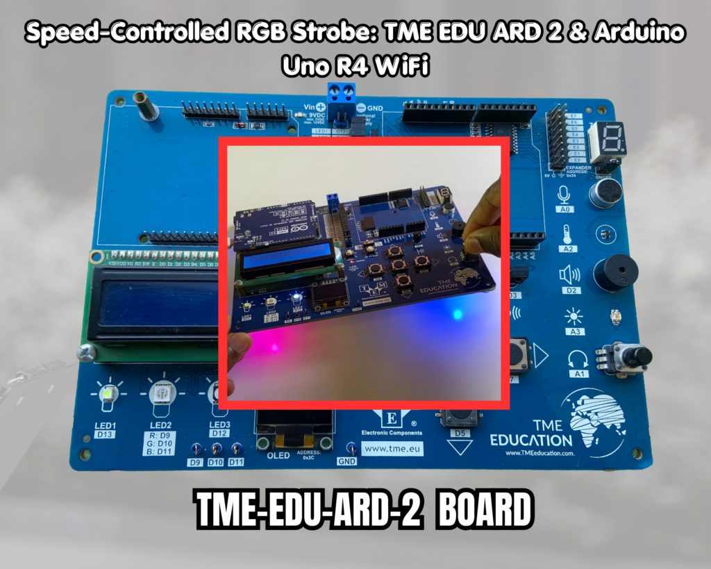
This project was supported by TME Education, an initiative dedicated to empowering people through electronics and technology education in underserved regions across Africa and India. Through their support with hardware, tools, and learning materials, they help build practical tech skills where access to educational resources is limited.
What is the TME EDU ARD 2 Board?
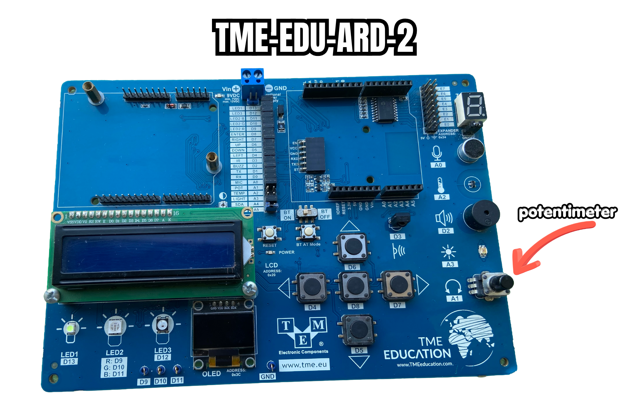
To make studying embedded systems easier, TME (Transfer Multisort Elektronik) created the TME EDU ARD 2, an all-in-one educational baseboard. The TME EDU ARD 2 incorporates necessary input and output components directly onto a single PCB, eliminating the need for unsecured jumper wires and breadboards.
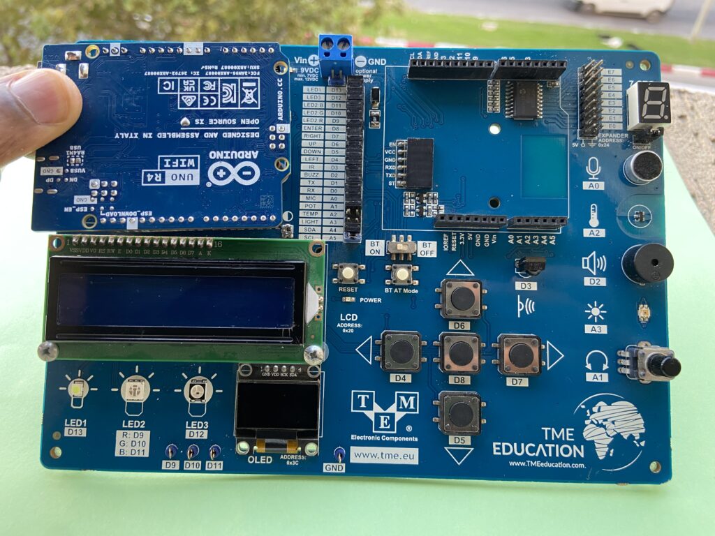
The board’s primary onboard features consist of:
- 5x Addressable RGB LEDs (NeoPixels): Connected to Digital Pin 12.
- Potentiometer: Connected to Analog Pin A1 for analog voltage control.
- User Pushbuttons & Navigation Switches: For digital inputs.
- LCD Display & 7-Segment Display: For visual outputs.
- Environmental Sensors: Light, temperature, and microphone modules.
- Standard Arduino Uno Header: Allows seamless mounting of any Arduino Uno-compatible mainboard underneath.
The Brain: Arduino Uno R4 WiFi
We utilize the Arduino Uno R4 WiFi to power our arrangement. Although it has 5V logic headers and the traditional Uno R3 physical size, it has a significant performance boost beneath the hood:
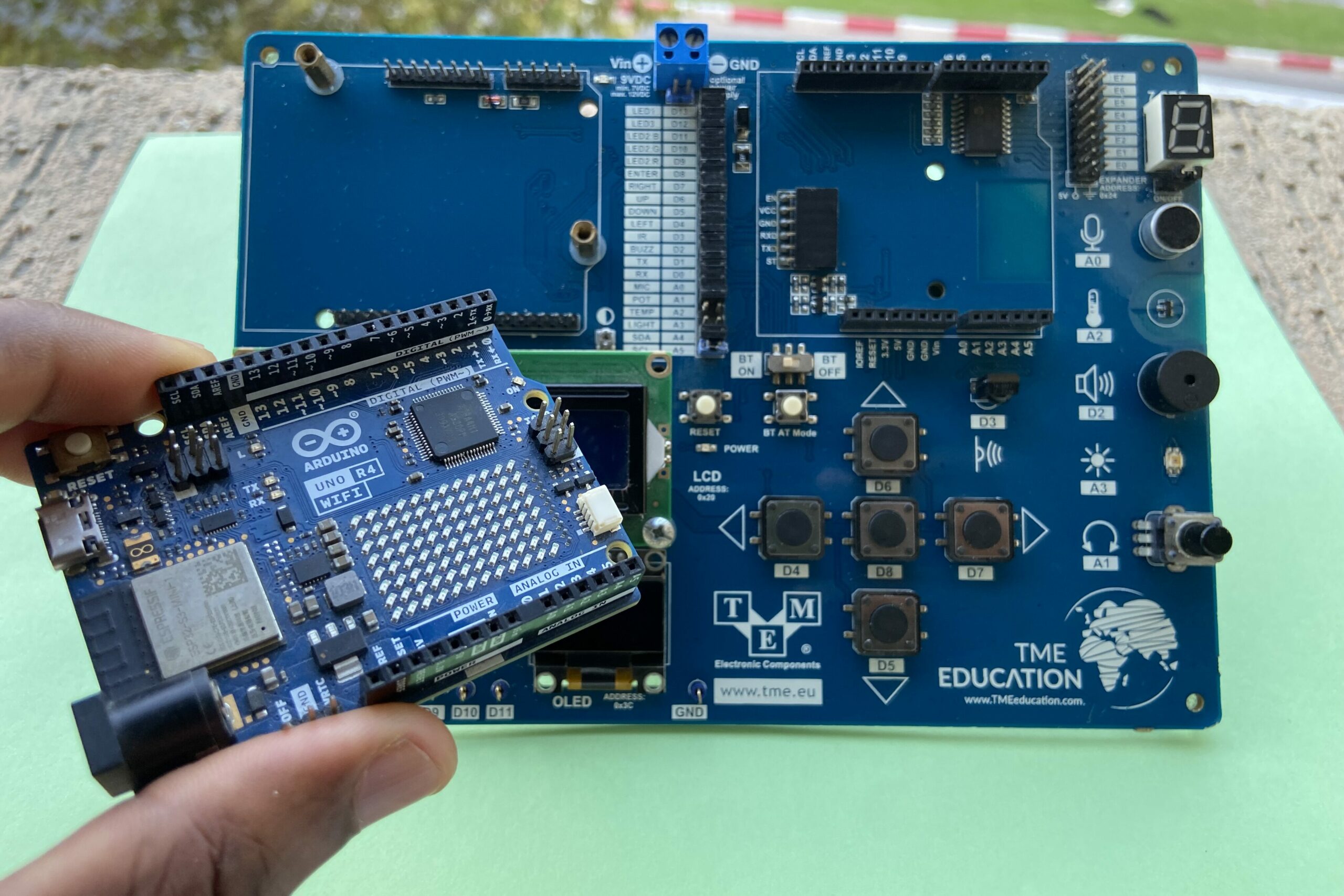
- 32-bit Microcontroller: Powered by the Renesas RA4M1 (Arm Cortex-M4) running at 48 MHz (16x faster than the Uno R3).
- ESP32-S3 Co-processor: Handles 2.4 GHz Wi-Fi and Bluetooth 5.0 connectivity.
- 12×8 LED Matrix: Onboard red LED matrix for displaying icons and animations.
- Expanded Memory: 256 KB Flash and 32 KB SRAM for complex software libraries.
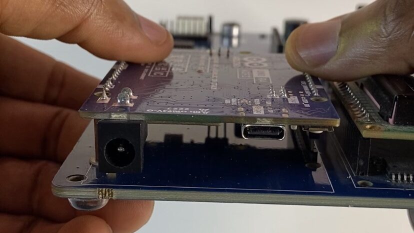
The Uno R4 WiFi fits directly into the TME EDU ARD 2 board without any modifications since it retains complete hardware pin compatibility with conventional Uno shields.
Hardware & Library Requirements
Components Used
| Component | Function / Location |
| Arduino Uno R4 WiFi | Main microcontroller board |
| TME EDU ARD 2 | Educational baseboard carrying peripherals |
| WS2812B RGB NeoPixels (x5) | Integrated on TME board (Data pin: D12) |
| Potentiometer | Integrated on TME board (Signal pin: A1) |
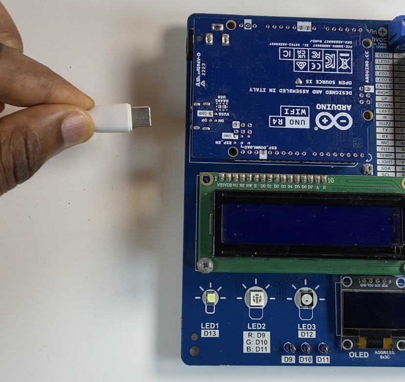
| USB-C Cable | Power and programming interface |
Library to Install
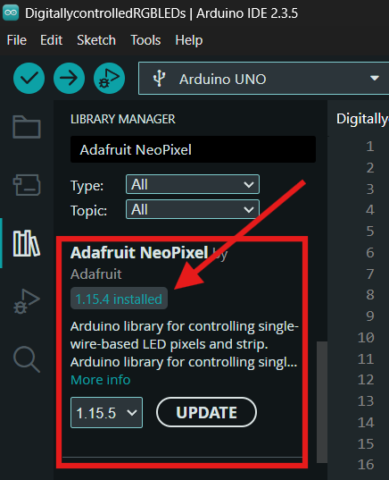
To control the RGB LEDs, you need the Adafruit NeoPixel library.
- Open the Arduino IDE.
- Go to Sketch ➡️Include Library ➡️ Manage Libraries… (or press
Ctrl+Shift+I/Cmd+Shift+I). - Search for Adafruit NeoPixel.
- Click Install (select “Install All” if prompted for dependencies).
Connect the Arduino Uno R4 WIFI on top of the TME-EDU-ARD-2
Connect the Type-C cable to Arduino Uno R4 WIFI
The Arduino Code
Using the Arduino IDE, upload the following sketch to your Arduino Uno R4 WiFi:
#include <Adafruit_NeoPixel.h>

// Create a NeoPixel object (5 LEDs, connected to Pin 12)
Adafruit_NeoPixel pixels = Adafruit_NeoPixel(5, 12, NEO_GRB + NEO_KHZ800);

void setup() {
  pixels.begin();

  // Set the first pixel (index 0) to a faint background color
  pixels.setPixelColor(0, pixels.Color(10, 20, 30));
  pixels.show();
}

void loop() {
  // Read the potentiometer voltage on Analog Pin A1 (0 to 1023)
  int potDelay = analogRead(1);

  // State 1: Odd pixels blue, even pixels red
  pixels.setPixelColor(1, pixels.Color(0, 0, 255));
  pixels.setPixelColor(2, pixels.Color(255, 0, 0));
  pixels.setPixelColor(3, pixels.Color(0, 0, 255));
  pixels.setPixelColor(4, pixels.Color(255, 0, 0));
  pixels.show();
  delay(potDelay);

  // State 2: Swap colors (odd red, even blue)
  pixels.setPixelColor(1, pixels.Color(255, 0, 0));
  pixels.setPixelColor(2, pixels.Color(0, 0, 255));
  pixels.setPixelColor(3, pixels.Color(255, 0, 0));
  pixels.setPixelColor(4, pixels.Color(0, 0, 255));
  pixels.show();
  delay(potDelay);
}
How it works
Pin A1 on the TME board’s integrated potentiometer provides an analog signal that the Arduino Uno R4 WiFi continually reads. The physical location of the knob is translated into a dynamic time delay value between 0 and 1023 milliseconds.
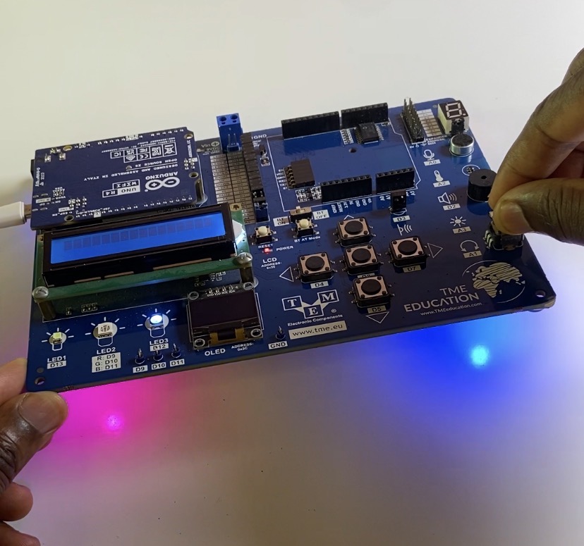
The code cycles between red and blue color patterns on four addressable RGB LEDs on pin D12 using the Adafruit NeoPixel library. The timing of these color swaps is directly controlled by the observed delay value, which enables real-time manual strobe speed adjustment.