
Wireless Temperature and Humidity Monitoring with ESP-NOW: Automating a 12V DC Fan via ESP32
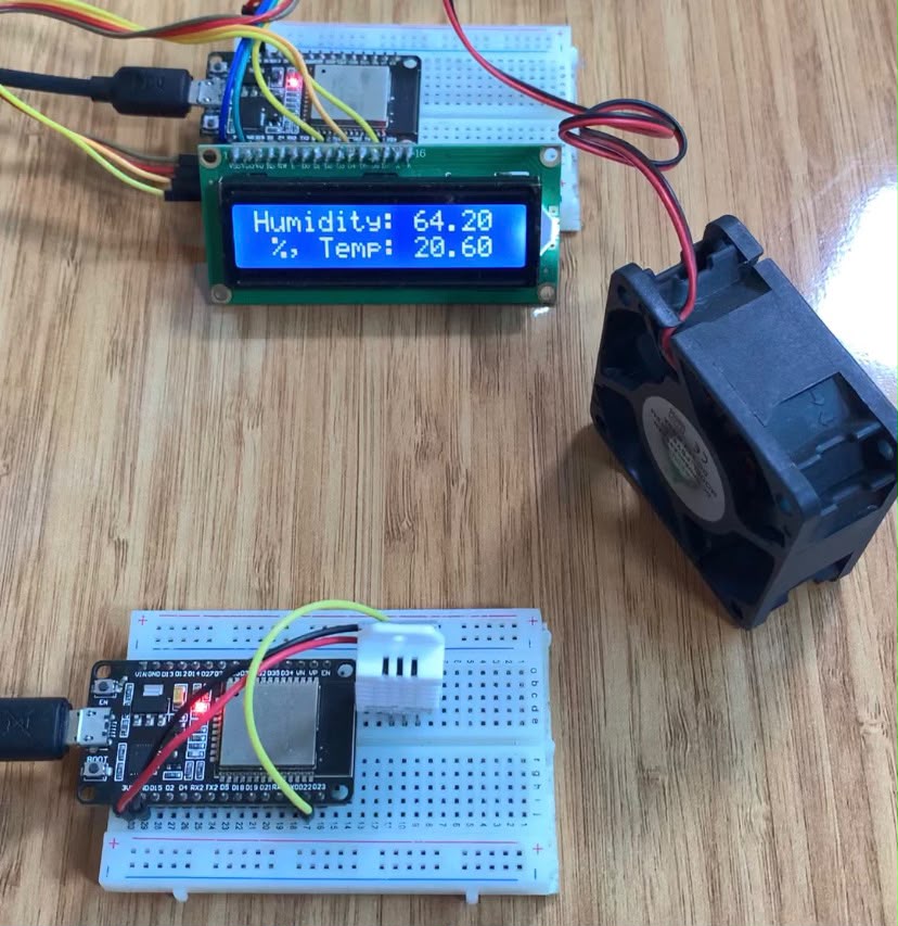
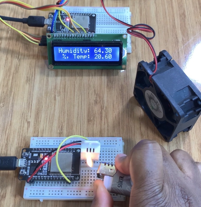
Discover how to use two ESP32 microcontrollers and the ESP-NOW protocol to create a peer-to-peer wireless climate monitoring and control system. A DHT22 sensor on a transmitter node provides real-time temperature and humidity readings, which are then streamed straight to a receiver node. When temperatures exceed predetermined limits, the receiver toggles a 5V relay module to activate a 12V DC cooling fan and shows real-time metrics on an I2C LCD screen.
Watch the Video
For written instructions, continue reading this page, or watch the video guide.
Components Used
Transmitter (Tx) Node:
- 1x ESP32 Development Board
- 1x DHT22 (AM2302) Temperature & Humidity Sensor
- Breadboard and Jumper Wires
Receiver (Rx) Node:
- 1x ESP32 Development Board
- 1x 16×2 LCD Module with I2C Backpack (PCF8574)
- 1x 5V Single-Channel Relay Module
- 1x 12V DC Fan
- 1x 12V DC External Power Supply
- Breadboard and Jumper Wires
Transmiter node: ESP32 & DHT2 Sensor
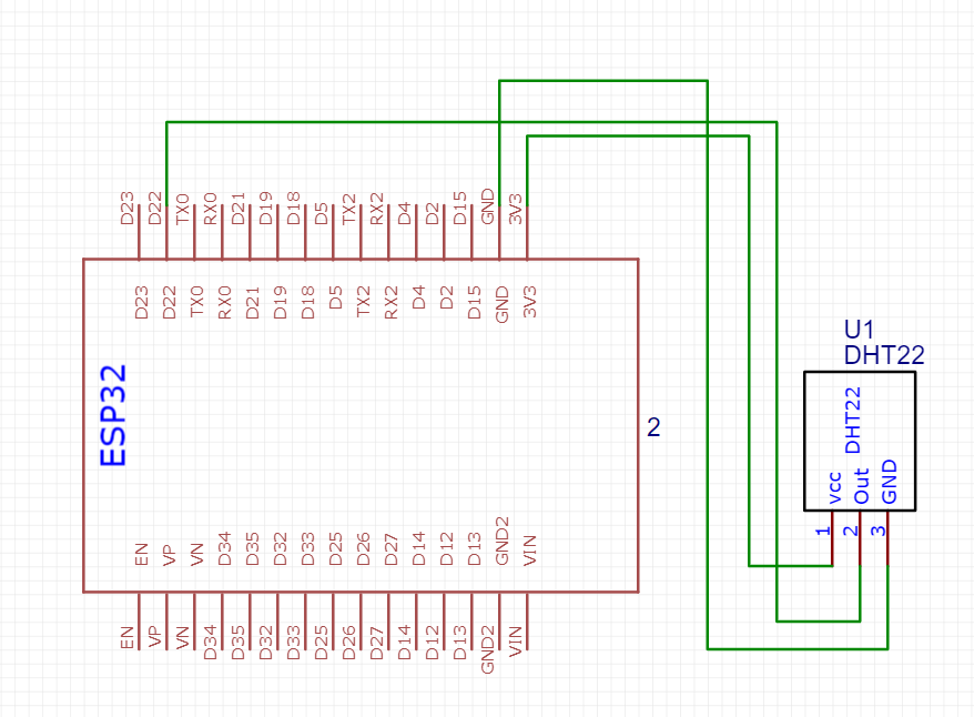
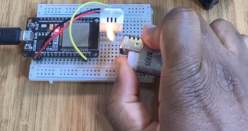
The ESP32’s 3.3V rail powers a DHT22 digital sensor used by the Transmitter node to measure temperature and humidity.
| DHT22 | ESP32 |
| GND | GND |
| OUT | GPIO 22 |
| VCC | 3.3V |
Receiver Node: ESP32, Relay Module & 12V DC Fan
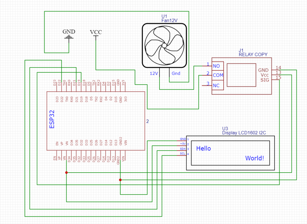
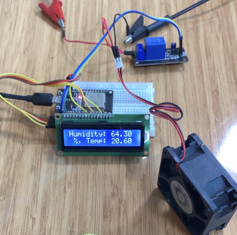
Incoming ESP-NOW telemetry packets are processed by the Receiver node, which also renders temperature and humidity readings on the 16×2 I2C LCD and toggles GPIO 19 to activate the 5V relay that controls the 12V DC fan.
| ESP32 | I2C LCD Display | 5V Relay Module | 12V DC Fan | Power Supply(+) | Power Supply(-) |
| VIN | VCC | ||||
| GND | GND | ||||
| SDA | GPIO 21 | ||||
| SCL | GPIO 22 | ||||
| 5V (VIN) | VCC | ||||
| GND | GND | ||||
| GPIO 19 | IN | ||||
| COM | + | ||||
| NO | + | ||||
| – | – |
Arduino C++ Code Setup (Peer-to-Peer Data Packets)
Transmitter Code (Tx)
#include <esp_now.h>
#include <WiFi.h>
#include "DHT.h"

#define DHTPIN 22     // Digital pin connected to the DHT sensor
#define DHTTYPE DHT22   // DHT 22 (AM2302)
DHT dht(DHTPIN, DHTTYPE);

// REPLACE WITH YOUR RECEIVER MAC Address
uint8_t broadcastAddress[] = {0x24, 0x62, 0xAB, 0xE0, 0xE7, 0x94};

struct __attribute__((packed)) dataPacket {
  float hum;   // Stores humidity value
  float temp;  // Stores temperature value
};

esp_now_peer_info_t peerInfo;

void OnDataSent(const uint8_t *mac_addr, esp_now_send_status_t status) {
  Serial.print("\r\nLast Packet Send Status:\t");
  Serial.println(status == ESP_NOW_SEND_SUCCESS ? "Delivery Success" : "Delivery Fail");
}

void setup() {
  Serial.begin(115200);
  Serial.println(F("DHTxx test!"));
  dht.begin();

  WiFi.mode(WIFI_STA);

  if (esp_now_init() != ESP_OK) {
    Serial.println("Error initializing ESP-NOW");
    return;
  }

  esp_now_register_send_cb(OnDataSent);

  memcpy(peerInfo.peer_addr, broadcastAddress, 6);
  peerInfo.channel = 0;
  peerInfo.encrypt = false;

  if (esp_now_add_peer(&peerInfo) != ESP_OK){
    Serial.println("Failed to add peer");
    return;
  }
}

void loop() {
  dataPacket packet;

  float h = dht.readHumidity();
  float t = dht.readTemperature();
  float f = dht.readTemperature(true);

  packet.hum = h;
  packet.temp = t;

  esp_err_t result = esp_now_send(broadcastAddress, (uint8_t *) &packet, sizeof(packet));
  delay(30);

  if (result == ESP_OK) {
    Serial.println("Sent with success");
  } else {
    Serial.println("Error sending the data");
  }

  if (isnan(h) || isnan(t) || isnan(f)) {
    Serial.println(F("Failed to read from DHT sensor!"));
    return;
  }

  float hif = dht.computeHeatIndex(f, h);
  float hic = dht.computeHeatIndex(t, h, false);

  Serial.print(F("Humidity: "));
  Serial.print(h);
  Serial.print(F("%  Temperature: "));
  Serial.print(t);
  Serial.print(F("°C "));
  Serial.print(f);
  Serial.print(F("°F  Heat index: "));
  Serial.print(hic);
  Serial.print(F("°C "));
  Serial.print(hif);
  Serial.println(F("°F"));

  delay(2000);
}
Receiver Code (Rx)
#include <esp_now.h>
#include <WiFi.h>
#include <LiquidCrystal_I2C.h>

#define Fan 19
LiquidCrystal_I2C lcd(0x27, 16, 2);

struct __attribute__((packed)) dataPacket {
  float hum;   // Stores humidity value
  float temp;  // Stores temperature value
};

void OnDataRecv(const esp_now_recv_info* info, const uint8_t *incomingData, int len) {
  dataPacket packet;

  memcpy(&packet, incomingData, sizeof(packet));

  lcd.setCursor(0, 0);
  lcd.print("Humidity: ");
  lcd.print(packet.hum);

  lcd.setCursor(0, 1);
  lcd.print(" %, Temp: ");
  lcd.print(packet.temp);
  lcd.print(" Celsius");

  delay(2000); // Delay 2 sec
  Serial.println(packet.temp);

  // Active Low Relay logic: LOW triggers relay ON, HIGH turns relay OFF
  if (packet.temp >= 21.60) {
    digitalWrite(Fan, LOW);
  } else {
    digitalWrite(Fan, HIGH);
  }
}

void setup() {
  lcd.init();
  lcd.backlight();
  Serial.begin(115200);

  pinMode(Fan, OUTPUT);
  digitalWrite(Fan, HIGH); // Ensure relay is OFF at start

  WiFi.mode(WIFI_STA);

  if (esp_now_init() != ESP_OK) {
    Serial.println("Error initializing ESP-NOW");
    return;
  }

  esp_now_register_recv_cb(OnDataRecv);
}

void loop() {
  // ESP-NOW relies on callback events; loop remains idle
}
How It Works
Protocol Initialization: To take advantage of ESP-NOW’s raw IEEE 802.11 MAC frame layer, both ESP32 modules set up Wi-Fi in Station Mode (WIFI_STA). As a result, a central Wi-Fi router or access point is no longer required.
Data Acquisition & Struct Packing: Every two seconds, the Transmitter takes temperature and humidity readings from the DHT22 sensor. Standard byte alignment (attribute((packed))) is used to pack the contents into a corresponding binary C-struct (dataPacket).
Peer Transmission: Using esp_now_send(), the Tx board sends the binary payload straight to the Rx board’s distinct MAC address.
Data Unpacking & Screen Output: The Rx board initiates the OnDataRecv callback method upon arrival. It writes real-time measurements to the I2C LCD screen and uses memcpy() to deserialize the memory payload back into variables.
Relay & Fan Control Logic: During the receive event, the Rx board evaluates the temperature value:
In order to complete the circuit and power the 12V DC fan, GPIO 19 drives LOW when the temperature rises above 21.60 °C, turning the active-low relay module ON.
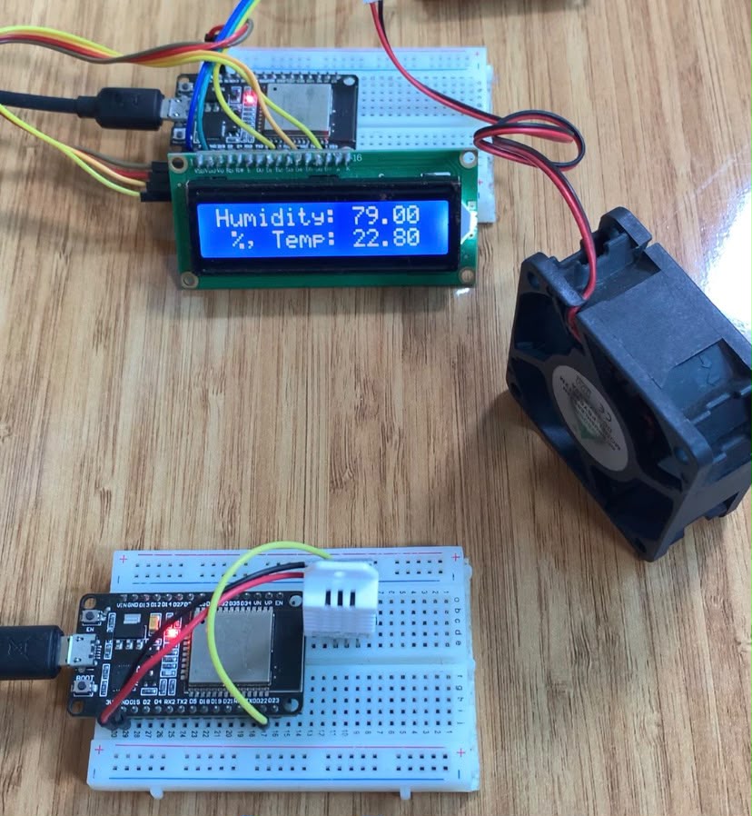
GPIO 19 hits HIGH, opening the relay contacts and shutting off the cooling fan when the temperature falls below 21.60 °C.