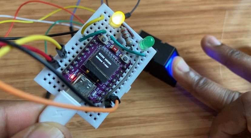

Biometric Access Control: ESP32-C3 OLED & AS608 Fingerprint Scanner
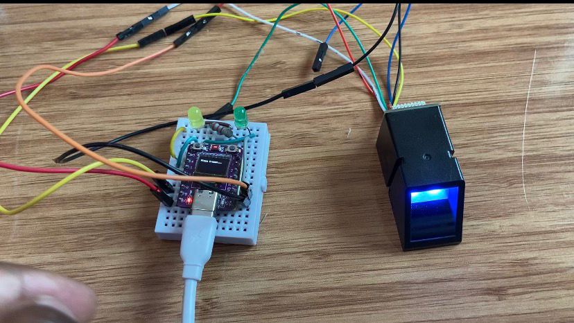
Using the little ESP32-C3 board and its integrated 0.42-inch OLED display, create an intelligent biometric authentication system. When paired with an AS608 optical fingerprint scanner, this project updates real-time progress messages on the screen and either signals unauthorized access using a Yellow LED or authorizes access via a Green LED when a matched print is scanned.
Components Used
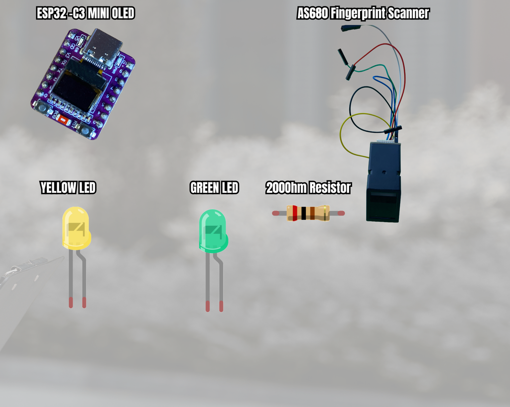
- ESP32-C3 Development Board with built-in 0.42″ (72×40) SSD1306 OLED
- Biometric Sensor: AS608 Optical Fingerprint Module
- Green LED (Access Granted)
- Yellow LED (Access Denied)
- 220Ω Resistor
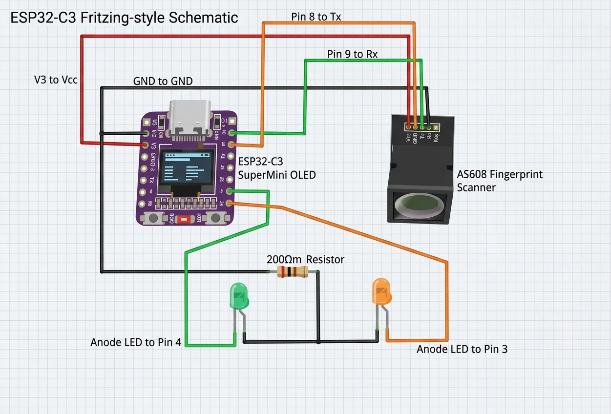
Circuit Wiring & Schematic Description
Required Libraries
Using the Arduino IDE Library Manager (Ctrl+Shift+I or Cmd+Shift+I), install these libraries:
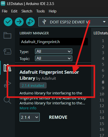
Adafruit Fingerprint Sensor Librar
Handles UART communication and image searching for AS608 modules
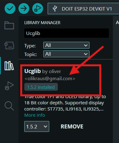
U8g2 library
Renders images and text on monochrome OLED screens (SSD1306 72×40).
Arduino Code
#include <Adafruit_Fingerprint.h>
#include <HardwareSerial.h>
#include <Wire.h>
#include <U8g2lib.h>

// Built-in 0.42" (72x40) SSD1306 OLED setup for ESP32-C3
// SCL = GPIO 6, SDA = GPIO 5
U8G2_SSD1306_72X40_ER_F_HW_I2C u8g2(U8G2_R0, /* reset=*/ U8X8_PIN_NONE, /* clock=*/ 6, /* data=*/ 5);

// Indicator LED Pins
#define Green_LED  4    // Authorized access
#define Yellow_LED 3    // Unauthorized access

// Hardware Serial for Fingerprint Sensor (UART 1)
// Sensor TX -> ESP32 RX (GPIO 8)
// Sensor RX -> ESP32 TX (GPIO 10)
#define FINGERPRINT_RX 8
#define FINGERPRINT_TX 10

HardwareSerial mySerial(1);
Adafruit_Fingerprint finger = Adafruit_Fingerprint(&mySerial);

// Forward declaration
uint8_t getFingerprintID(void);

void setup() {
  Serial.begin(115200);
  delay(100);

  // Initialize LEDs
  pinMode(Green_LED, OUTPUT);
  pinMode(Yellow_LED, OUTPUT);
  digitalWrite(Green_LED, LOW);
  digitalWrite(Yellow_LED, LOW);

  // Initialize U8g2 OLED
  u8g2.begin();
  u8g2.clearBuffer();
  u8g2.setFont(u8g2_font_micro_tr);
  u8g2.setCursor(0, 12);
  u8g2.print("Fingerprint Init...");
  u8g2.sendBuffer();

  // Initialize Serial and Fingerprint sensor
  mySerial.begin(57600, SERIAL_8N1, FINGERPRINT_RX, FINGERPRINT_TX);
  finger.begin(57600);

  u8g2.clearBuffer();
  if (finger.verifyPassword()) {
    Serial.println("Found fingerprint sensor!");
    u8g2.setCursor(0, 12);
    u8g2.print("Sensor Found!");
    u8g2.setCursor(0, 26);
    u8g2.print("Ready to scan");
  } else {
    Serial.println("Did not find fingerprint sensor :(");
    u8g2.setCursor(0, 12);
    u8g2.print("Sensor Error!");
    u8g2.sendBuffer();
    while (1) delay(1);
  }
  u8g2.sendBuffer();

  delay(2000);
}

void loop() {
  // Idle status on OLED
  u8g2.clearBuffer();
  u8g2.setFont(u8g2_font_micro_tr);
  u8g2.setCursor(0, 12);
  u8g2.print("Place Finger...");
  u8g2.sendBuffer();

  getFingerprintID();
  delay(1000);
}

uint8_t getFingerprintID() {
  uint8_t p = finger.getImage();
  if (p != FINGERPRINT_OK) return p;

  p = finger.image2Tz();
  if (p != FINGERPRINT_OK) return p;

  p = finger.fingerFastSearch();
  if (p == FINGERPRINT_OK) {
    // Authorized fingerprint
    Serial.print("Found ID #"); Serial.println(finger.fingerID);

    u8g2.clearBuffer();
    u8g2.setFont(u8g2_font_micro_tr);
    u8g2.setCursor(0, 12);
    u8g2.print("ACCESS GRANTED");
    u8g2.setCursor(0, 26);
    u8g2.print("ID: #");
    u8g2.print(finger.fingerID);
    u8g2.sendBuffer();

    digitalWrite(Green_LED, HIGH);
    delay(2000);
    digitalWrite(Green_LED, LOW);
  } else {
    // Unauthorized fingerprint
    Serial.println("This finger wasn't stored");

    u8g2.clearBuffer();
    u8g2.setFont(u8g2_font_micro_tr);
    u8g2.setCursor(0, 12);
    u8g2.print("ACCESS DENIED!");
    u8g2.setCursor(0, 26);
    u8g2.print("Unknown Finger");
    u8g2.sendBuffer();

    digitalWrite(Yellow_LED, HIGH);
    delay(2000);
    digitalWrite(Yellow_LED, LOW);
  }

  return p;
}
How it works
The AS608 sensor uses its integrated optical prism to continually search for a finger location. Once identified, it creates a distinct mathematical template and transforms the physical ridge pattern into a digital image.
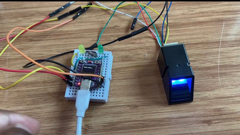
In order to compare this image data with pre-stored templates in the module’s flash memory, the ESP32-C3 transmits it via hardware serial pins GPIO 8 and GPIO 10. The system turns on the green LED on GPIO 4 and shows the matching ID number on the OLED when a rapid search match is verified.
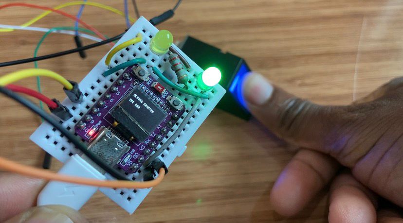
The module returns an error flag if the scanned print fails image conversion or does not match any stored data. After processing this response, the ESP32-C3 flashes an access denied alert on the screen and turns on the yellow LED on GPIO 3 for two seconds.