
Automated Light Monitoring System Using Arduino Uno R4 WiFi, TME EDU ARD Rev2 & Arduino IoT Cloud
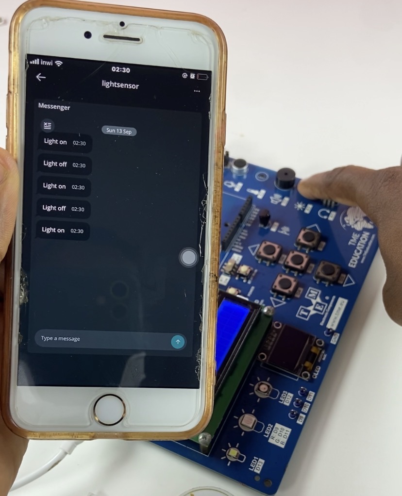
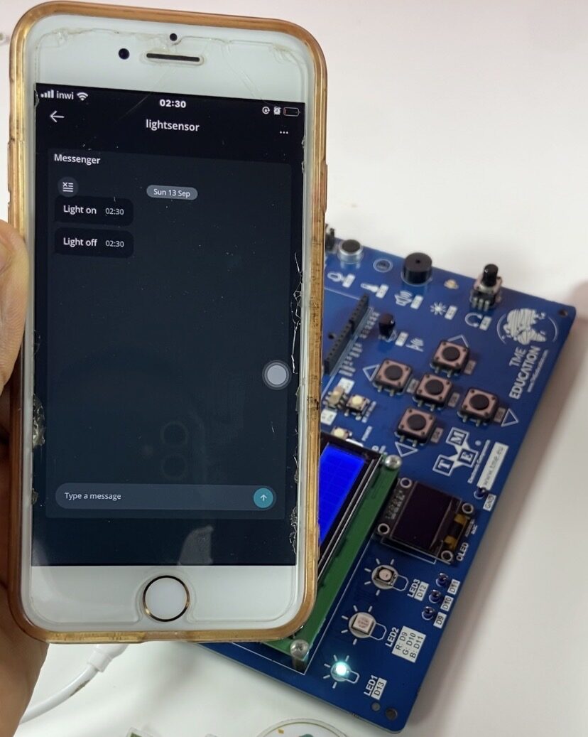
Utilize an ambient light sensor, built-in display, and cloud dashboard to automate your lighting management and remotely check light levels in real time! In this project, we use the Arduino Uno R4 WiFi in conjunction with the TME EDU ARD Rev2 board to send telemetry straight to the Arduino IoT Cloud, operate a local indicator LED, show real-time status text on an I2C LCD, and continually monitor ambient light levels.
This project was supported by TME Education, an initiative dedicated to empowering people through electronics and technology education in underserved regions across Africa and India. Through their support with hardware, tools, and learning materials, they help build practical tech skills where access to educational resources is limited.
Learn more about TME EDU ARD Rev2 board.
Components Used
- Arduino Uno R4 WiFi
- TME EDU ARD Rev2 board
- Onboard Light sensor connected to Pin
A3 - Onboard LED connected to Pin
13 - Onboard 16×2 I2C LCD
- USB-C Cable
Schematic & Circuit Layout
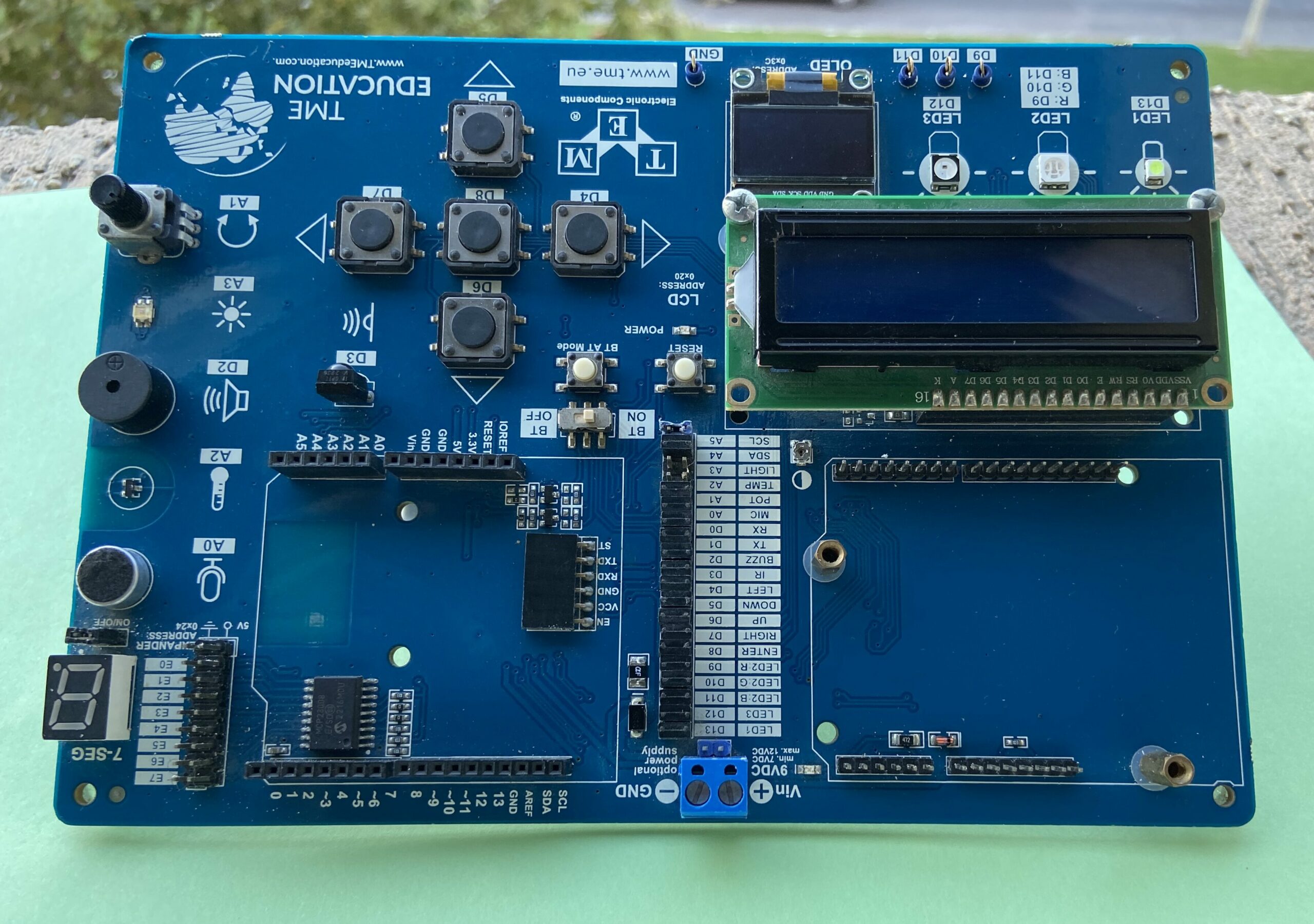
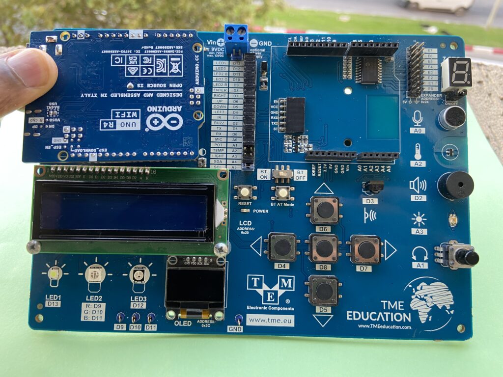
Designed to fit directly onto the Arduino header footprint, the TME EDU ARD Rev2 is a direct plug-and-play board.
- Board Stacking: Align all header pins and stack the Arduino Uno R4 WiFi board on top of the TME EDU ARD Rev2.
- The light sensor circuit on the board routes directly to Analog Pin A3.
- The onboard status LED routes to Digital Pin 13.
- The 16×2 LCD communicates with the MCU over SDA and SCL lines via an onboard MCP23008 port expander at I2C address
Required Libraries
hd44780 library
Handles communication with the MCP23008 I2C expander driving the 16×2 LCD

ArduinoIoTCloud library

Arduino IoT Cloud Setup
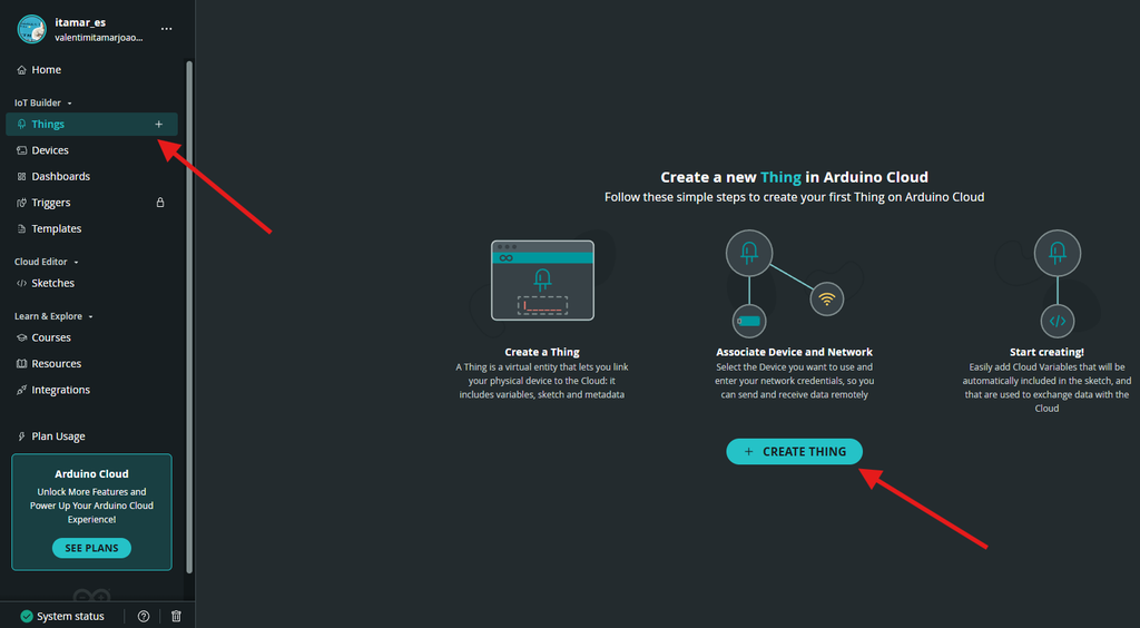
Create and Name the Thing
Navigate to Arduino IoT Cloud, create a new Thing, and rename it to your preferred project name.
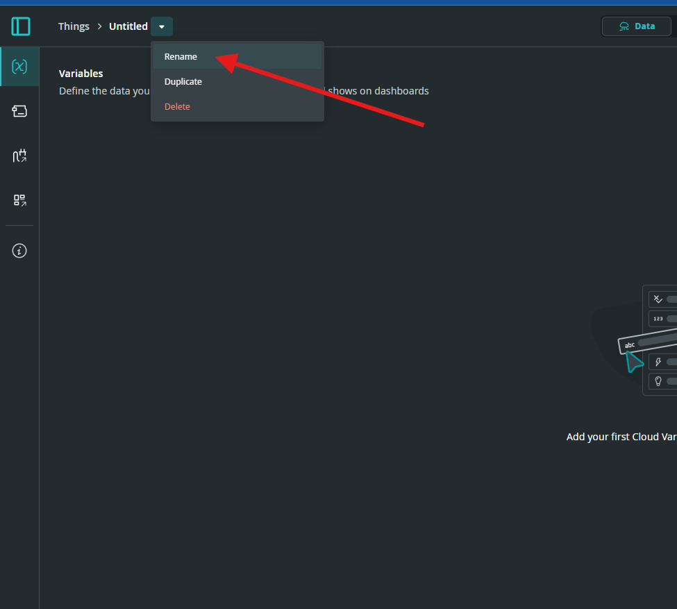
Renaming the thing the Thing will be called lightsensor.
Create a Variable
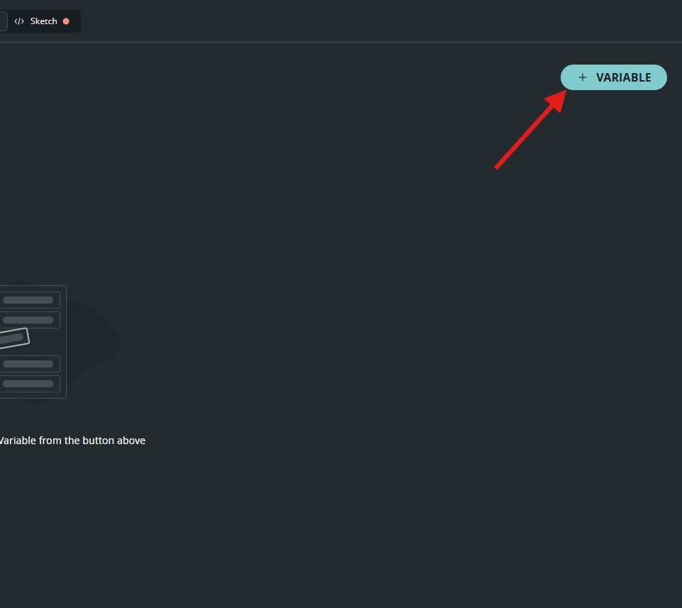
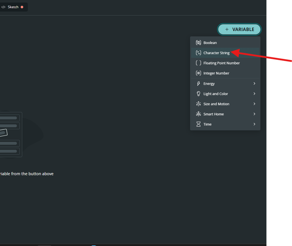
Add a new variable to your Thing (such as a String variable) to handle your data transmission.
The variable is a character String called lightsensor, and it’s read-only.
Associate or Create a Device
Choose to create a new device on Arduino IoT Cloud and set it up via serial USB connected to the detected device.
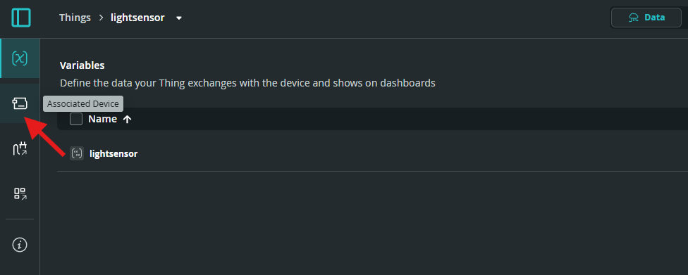
Click on New Device.
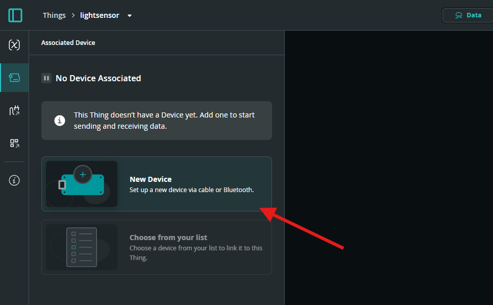
We are using an Arduino board, Arduino Uno R4 WiFi.
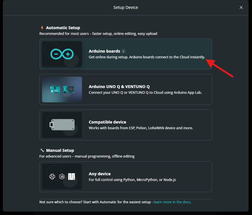
Pair and Configure the Device
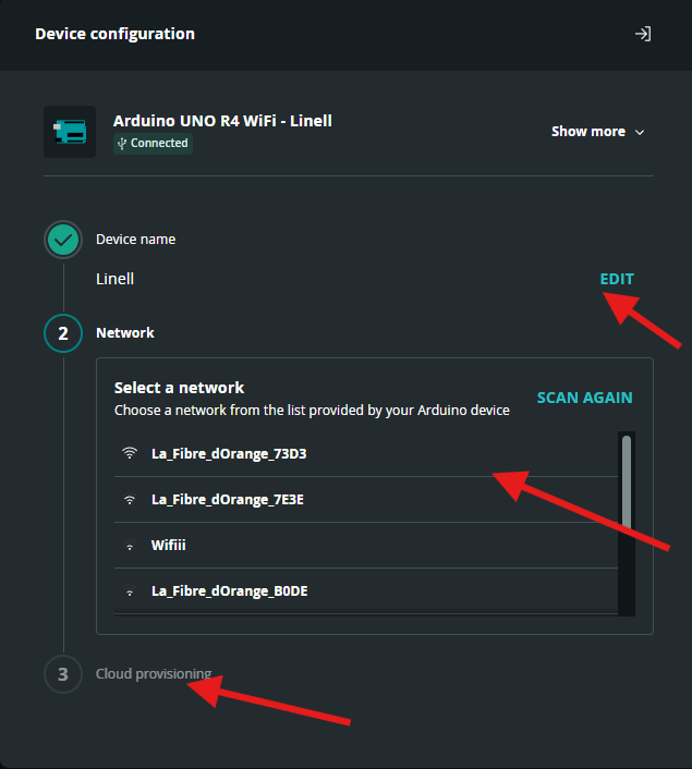
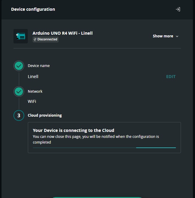
Complete the device pairing process, continue to connect the device, update the board if prompted, change the device name, choose your Wi-Fi network, and proceed through the processing screen.
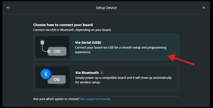
Connect the device via Serial Port.
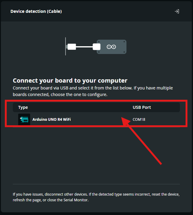
Pairing process
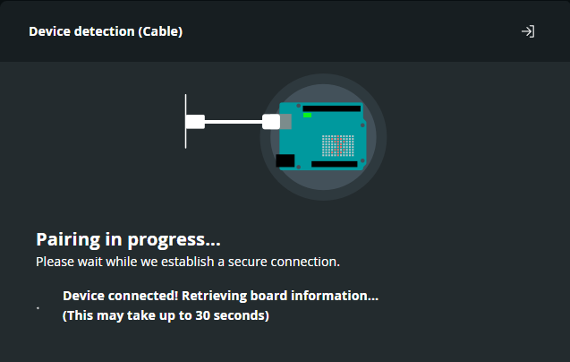
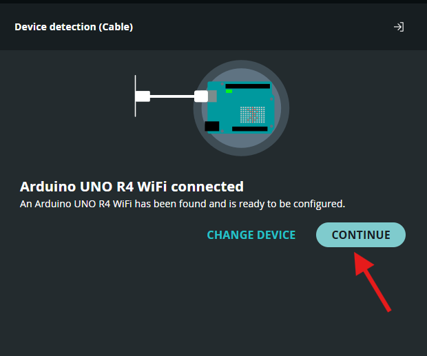
Continue to connect the device.
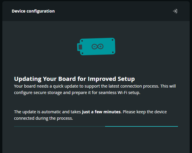
Updating the board for improved setup.
Change the device name, choose your Wi-Fi network, and proceed through the processing screen.
Create and Rename the Dashboard
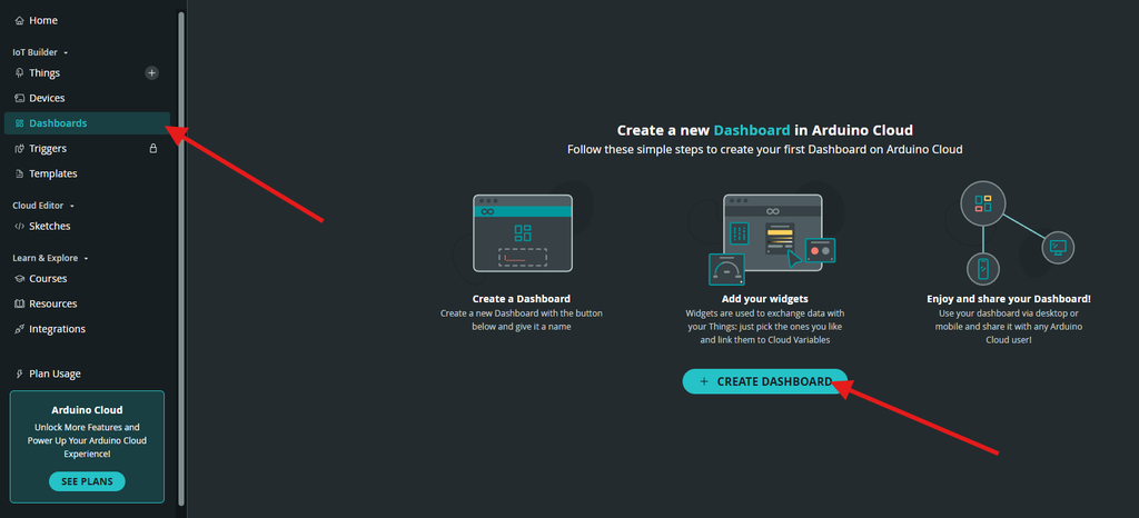
Create a new dashboard in Arduino IoT Cloud and rename it.
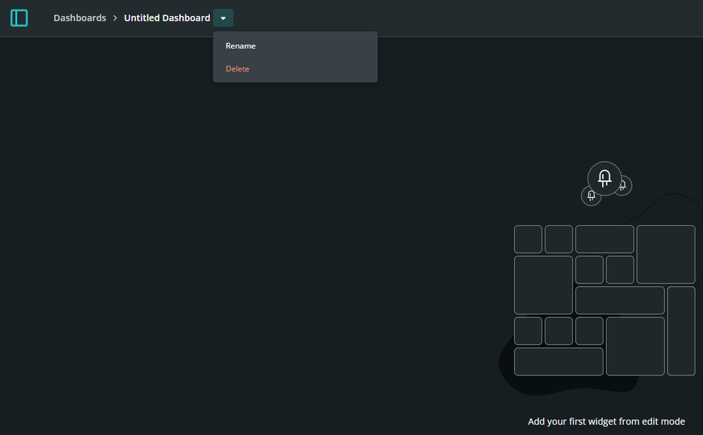
Rename the Dashboard.
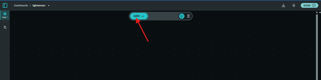
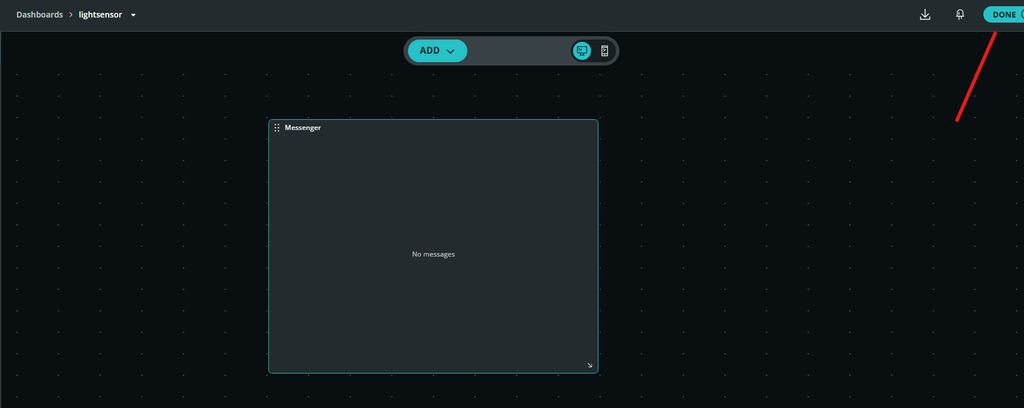
Add and Configure Widgets
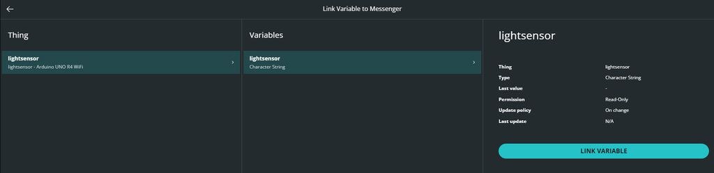
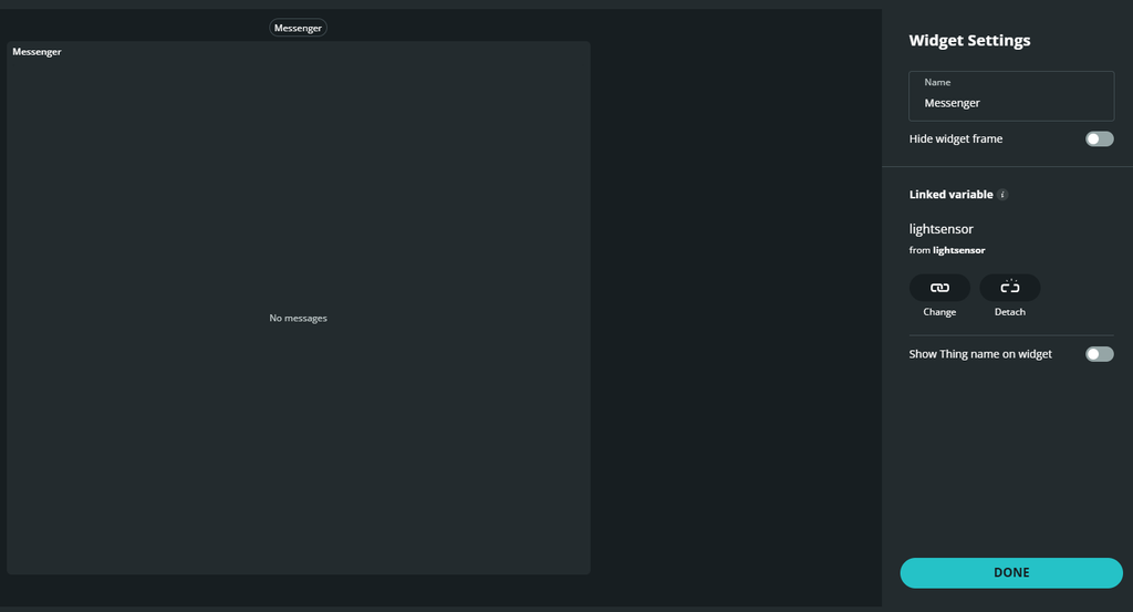
Add a message widget to your dashboard, connect your light sensor variable to the widget, and finalize your Arduino sketch.
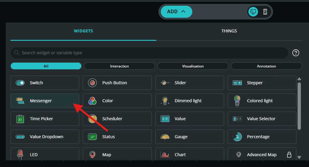
Connect your light sensor.
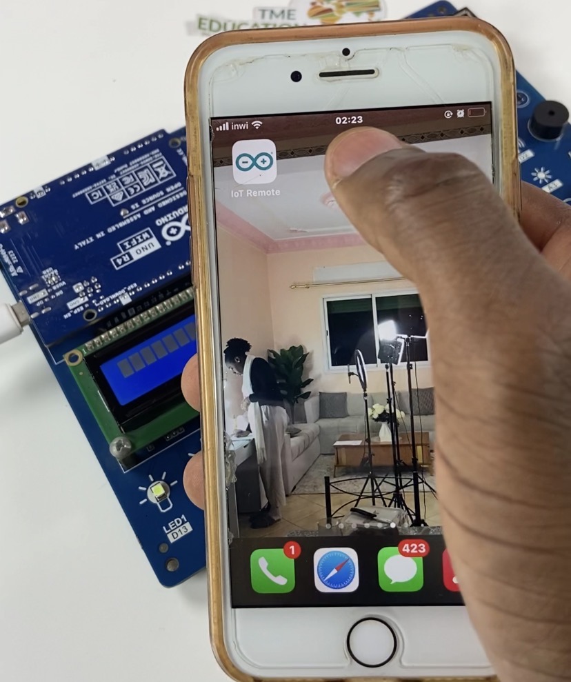
IoT Remote Mobile App
Download the IoT Remote mobile app, log in, and connect to your Arduino IoT Cloud. No configuration is needed the project is already set up and ready to go if you use the same Arduino IoT Cloud account.
Arduino Code
#include <Wire.h>
#include <hd44780.h>
#include <hd44780ioClass/hd44780_I2Cexp.h>
#include "thingProperties.h"

// LCD configuration for TME EDU ARD Rev2 (MCP23008 expander at address 0x20)
hd44780_I2Cexp lcd(0x20, I2Cexp_MCP23008, 7, 6, 5, 4, 3, 2, 1, HIGH);

const int LIGHT_PIN = A3; // Light sensor connected to analog pin A3
const int LED_PIN = 13;   // LED connected to pin 13

void setup() {
  // Initialize serial monitor
  Serial.begin(9600);
  delay(1500);

  // Defined in thingProperties.h
  initProperties();

  // Connect to Arduino IoT Cloud
  ArduinoCloud.begin(ArduinoIoTPreferredConnection);

  pinMode(LIGHT_PIN, INPUT);
  pinMode(LED_PIN, OUTPUT);

  // Initialize the LCD
  lcd.begin(16, 2);
  lcd.clear();

  setDebugMessageLevel(2);
  ArduinoCloud.printDebugInfo();
}

void loop() {
  ArduinoCloud.update();

  // Read analog value from photoresistor on pin A3
  int lightValue = analogRead(LIGHT_PIN);

  // Check light sensor reading against threshold (800)
  if (lightValue > 800) {
    // Threshold met: High ambient light detected
    lightsensor = "Light off";
    digitalWrite(LED_PIN, LOW);   // Pin 13 LOW

    // Print "Light off" on LCD
    lcd.clear();
    lcd.setCursor(0, 0);
    lcd.print("Light off");
  } else {
    // Threshold NOT met: Absence of light
    lightsensor = "Light on";
    digitalWrite(LED_PIN, HIGH);  // Pin 13 HIGH

    // Print "Light on" on LCD
    lcd.clear();
    lcd.setCursor(0, 0);
    lcd.print("Light on");
  }

  // Debugging output to Serial Monitor
  Serial.print("Light Sensor Reading: ");
  Serial.print(lightValue);
  Serial.print(" | Status: ");
  Serial.println(lightsensor);

  delay(1000); // Sample every 1 second
}

/*
  Executed when the 'lightsensor' string changes from the IoT Cloud Dashboard
*/
void onLightsensorChange() {
  // Dashboard override logic can be added here if needed
}
How It Works
Using the light sensor on pin A3, the Arduino Uno R4 WiFi on TME EDU ARD Rev2 board continually measures ambient light intensity and converts light levels into an analog voltage measurement between 0 and 1023.
The microcontroller initiates the automated lighting mode when ambient light decreases and the threshold is not reached (reading is 800 or below): It shows “Light on” on the MCP23008-driven 16×2 I2C LCD screen and drives Pin 13 HIGH to power the LED indication.
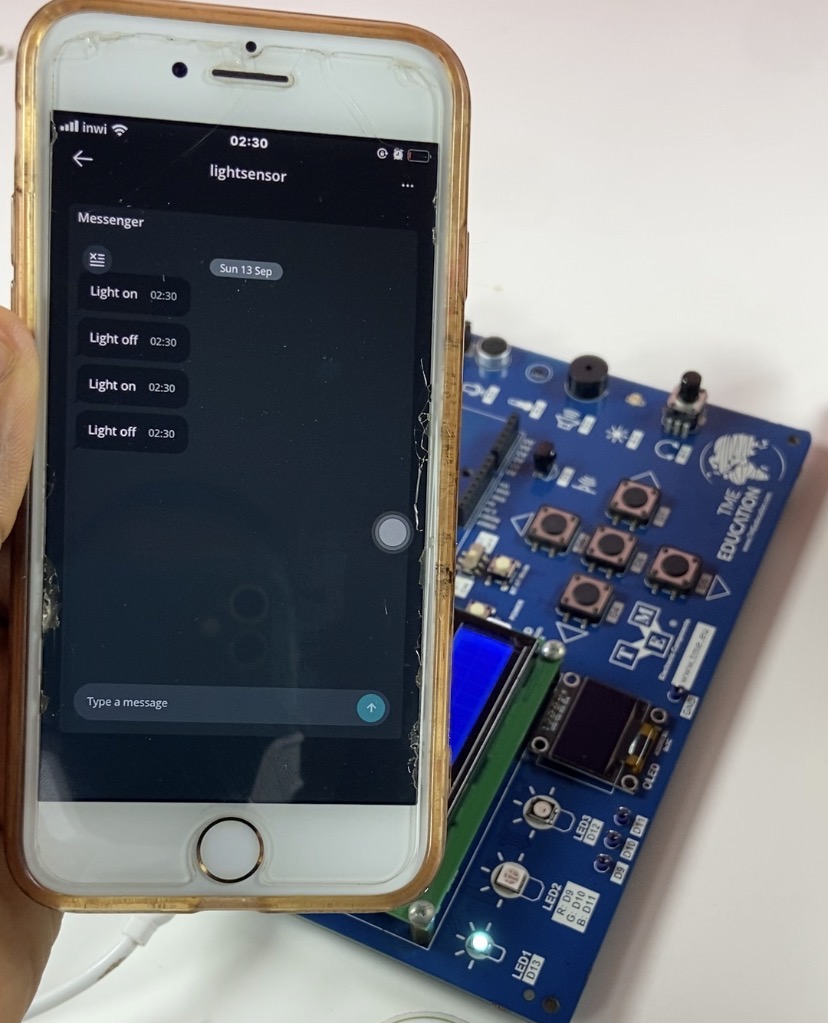
The board drives Pin 13 LOW to switch off the LED indicator and updates the LCD to show “Light off” when enough ambient light is detected and the threshold is reached (reading exceeds 800). For real-time remote tracking on your dashboard, ArduinoCloud.update() simultaneously sends the current status message to the Arduino IoT Cloud servers.