
DIY Wireless LED State and Brightness Control Using Arduino and LoRa SX1278
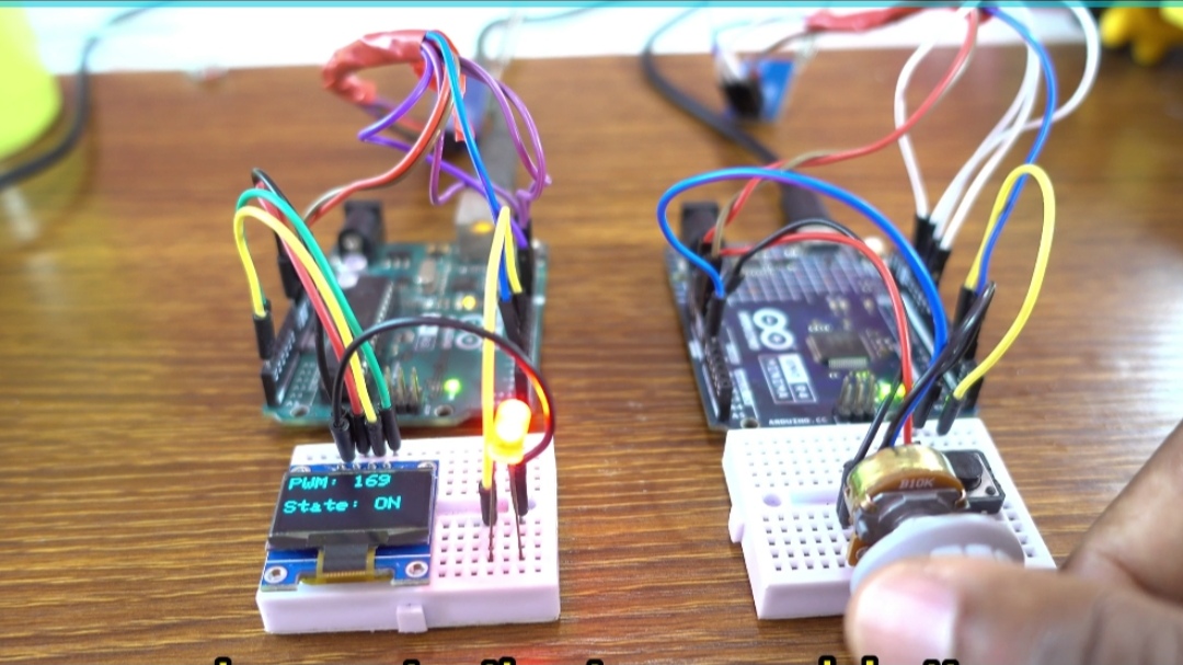
Numerous opportunities for industrial controls, remote monitoring, and smart home automation are made possible by wireless long-range control. In this project, we will use two LoRa SX1278 transceivers to construct a long-range wireless controller. With an Arduino Uno R4 Minima on the transmitter side and an Arduino Uno R3 on the receiver side, we can use a potentiometer to dynamically change an LED’s brightness or a pushbutton to quickly override its toggle status over long distances.
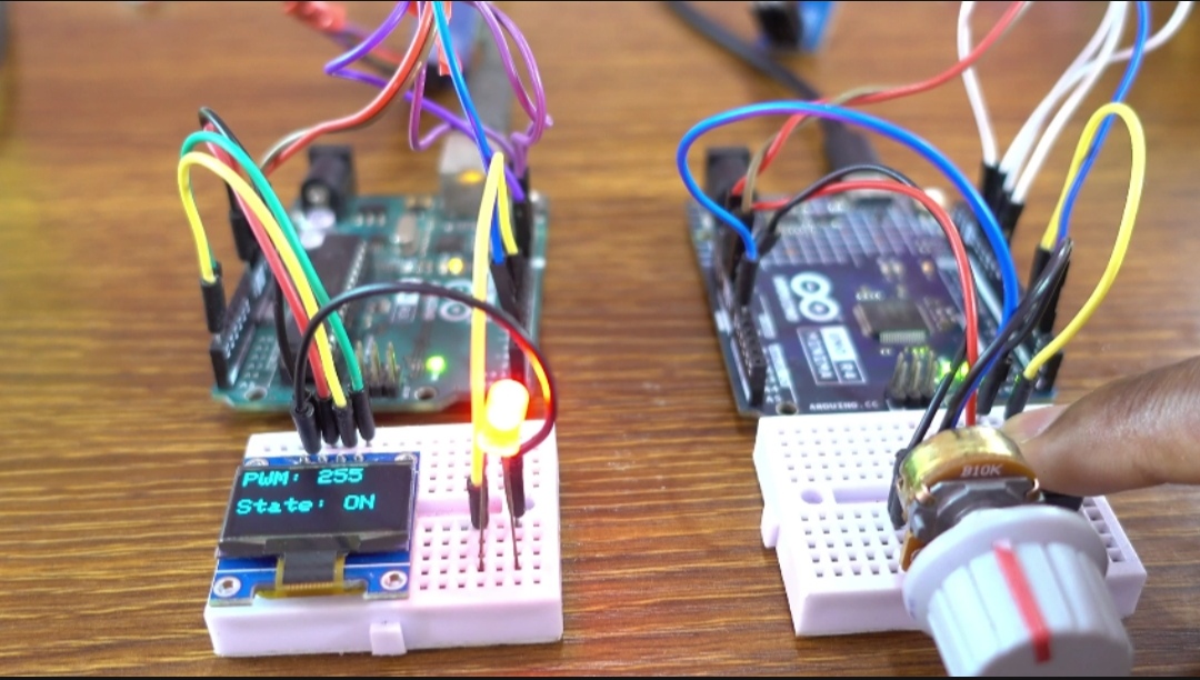
The receiver node has a 0.96-inch SSD1306 OLED display that shows the precise PWM duty cycle and the LED’s current status (ON or OFF) to provide us with real-time visual feedback. This project is a useful, hands-on reference for learning about remote PWM brightness control, CSV string parsing in C++, or LoRa packet communication.
Watch the full video
For written instructions, continue reading this page, or watch the video guide.
Components Used
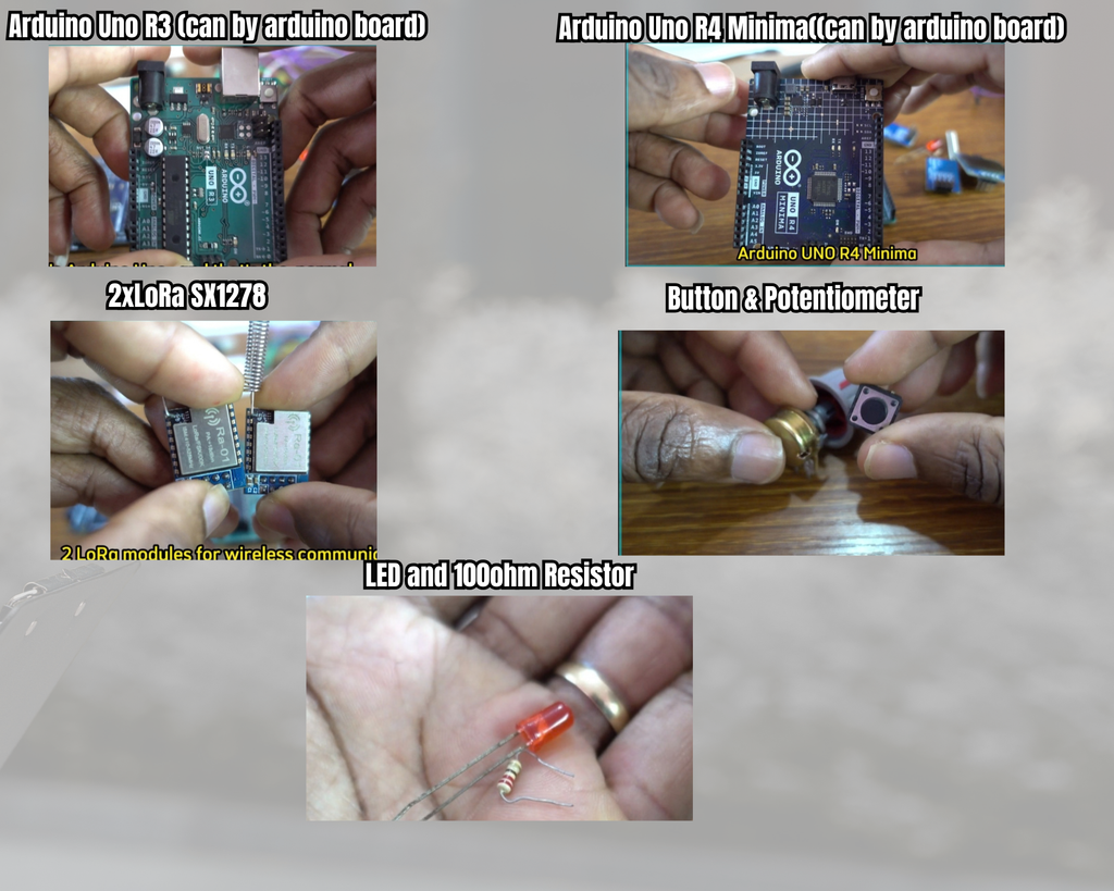
- Arduino Uno R4 Minima (Transmitter Node)
- Arduino Uno R3 (Receiver Node)
- LoRa SX1278 (433 MHz) Transceiver Modules
- 0.96-inch I2C SSD1306 OLED Display (128×64)
- Pushbutton Switch
- Standard LED (with a 100Ω resistor)
- 10kΩ Potentiometer
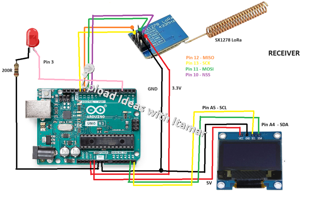
Circuit Schematic & Pin Wiring
Transmitter Side (Arduino Uno R4 Minima)

Receiver Side (Arduino Uno R3)
Required Arduino Libraries
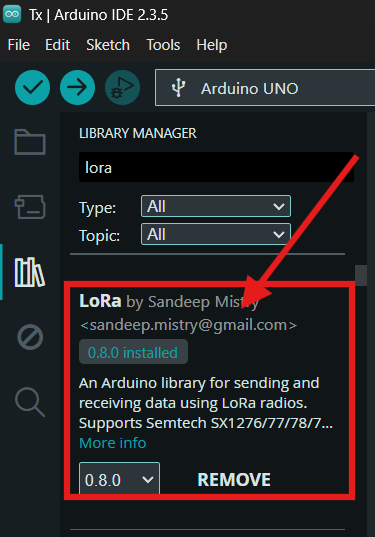
LoRa by Sandeep Mistry (For driving the SX1278 module over SPI)
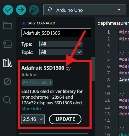
Adafruit SSD1306 by Adafruit (For display rendering)
Adafruit GFX Library by Adafruit (Core graphics library for OLED)

Arduino Code
Transmitter Code (Tx)
#include <SPI.h>
#include <LoRa.h>

int pot = A0;             // Analog pin for the potentiometer
int buttonPin = 4;        // Define the pin for the pushbutton
bool buttonState = false; // State of the pushbutton

void setup() {
  Serial.begin(9600);
  pinMode(pot, INPUT);
  pinMode(buttonPin, INPUT_PULLUP);  // Initialize pushbutton pin as input with pull-up resistor

  while (!Serial);
  Serial.println("LoRa Sender");

  if (!LoRa.begin(433E6)) { // Initialize LoRa at 433 MHz
    Serial.println("Starting LoRa failed!");
    while (1);
  }
}

void loop() {
  int potValue = analogRead(pot);  // Read the potentiometer value (0-1023)
  buttonState = (digitalRead(buttonPin) == LOW); // Read the pushbutton state (active LOW)

  // Format the data payload as "potValue,buttonState"
  String dataToSend = String(potValue) + "," + String(buttonState);

  Serial.print("Sending Data: ");
  Serial.println(dataToSend);

  // Send wireless LoRa packet
  LoRa.beginPacket();
  LoRa.print(dataToSend);
  LoRa.endPacket();

  delay(50);  // Sample & transmission interval
}
Receiver Code (Rx)
#include <SPI.h>
#include <LoRa.h>
#include <Adafruit_GFX.h>
#include <Adafruit_SSD1306.h>
#include <Wire.h>

// OLED display settings
#define SCREEN_WIDTH 128
#define SCREEN_HEIGHT 64
#define OLED_RESET    -1
Adafruit_SSD1306 display(SCREEN_WIDTH, SCREEN_HEIGHT);

int LED = 3;            // PWM pin connected to the LED
String inString = "";   // String buffer to hold incoming payload
int potValue = 0;
int pwmValue = 0;
bool ledState = false;  // Track the LED state (ON or OFF)

void setup() {
  Serial.begin(9600);
  pinMode(LED, OUTPUT);

  // Initialize OLED display with I2C address 0x3C
  if (!display.begin(SSD1306_SWITCHCAPVCC, 0x3C)) {
    Serial.println(F("SSD1306 allocation failed"));
    for (;;);  // Infinite loop if OLED initialization fails
  }

  display.display();
  delay(2000);  // Pause to display startup screen
  display.clearDisplay();

  while (!Serial);
  Serial.println("LoRa Receiver");

  if (!LoRa.begin(433E6)) { // Initialize LoRa at 433 MHz
    Serial.println("Starting LoRa failed!");
    while (1);
  }
}

void loop() {
  // Try to parse incoming LoRa packet
  int packetSize = LoRa.parsePacket();
  if (packetSize) {
    // Read packet characters into inString
    while (LoRa.available()) {
      int inChar = LoRa.read();
      inString += (char)inChar;
    }

    // Extract comma-separated values
    int commaIndex = inString.indexOf(',');
    if (commaIndex != -1) {
      String potString = inString.substring(0, commaIndex);
      String buttonString = inString.substring(commaIndex + 1);

      potValue = potString.toInt();              // Convert potentiometer value to integer
      bool buttonState = (buttonString == "1");  // Convert button state to boolean

      // Priority control: set full brightness if button is pressed, else map potentiometer
      if (buttonState) {
        pwmValue = 255;  // Force max brightness on button press
      } else {
        pwmValue = map(potValue, 0, 1023, 0, 255);  // Map 10-bit analog read to 8-bit PWM
      }

      // Determine LED active state based on resulting PWM value
      if (pwmValue > 0 || buttonState) {
        ledState = true;
      } else {
        ledState = false;
      }

      inString = "";  // Clear string buffer for the next packet

      // Update OLED display with updated values
      display.clearDisplay();
      display.setTextSize(2);
      display.setTextColor(SSD1306_WHITE);
      display.setCursor(0, 0);
      display.print("PWM: ");
      display.println(pwmValue);
      display.setCursor(0, 30);
      display.print("State: ");
      display.println(ledState ? "ON" : "OFF");
      display.display();

      Serial.print("Potentiometer Value: ");
      Serial.print(potValue);
      Serial.print(" -> PWM Value: ");
      Serial.print(pwmValue);
      Serial.print(" LED State: ");
      Serial.println(ledState ? "ON" : "OFF");
    }
  }

  // Write output to LED pin
  if (ledState) {
    analogWrite(LED, pwmValue);
  } else {
    digitalWrite(LED, 0);
  }
}
How It Works
The transmitter node serializes the readings from the pushbutton on pin 4 and the 10k potentiometer on pin A0 into a prepared CSV string (such as “512,0”) while continually monitoring the inputs. The LoRa SX1278 transceiver uses the SPI bus to send this payload over a long distance in the 433 MHz band. In order to identify the proper output parameters, the receiver node parses the incoming string at the comma delimiter after receiving the packet, separating the raw analog value and button status.
The receiver overrides standard control and immediately adjusts the LED brightness to maximum duty cycle (PWM 255) if the pushbutton status is high (1).
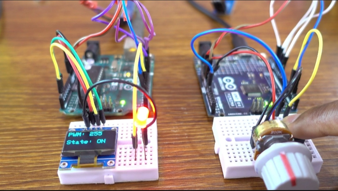
The LED attached to digital pin 3 is modulated in accordance with the system’s mapping of the 10-bit analog potentiometer value (0–1023) to an 8-bit PWM value (0–255) when the button is unpressed (0).