No Wi-Fi Needed! ESP-NOW PIR Motion Alarm with LED & Buzzer
In today’s blog, you are going to learn how to build a wireless motion alert system with an ESP8266 NodeMCU microcontroller and the ESPNow protocol communication.
Check the video below for demonstration
Components needed
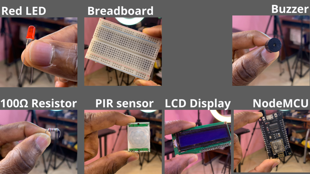
Below is the list of all components that we need for this project:
- 2xNodeMCU Boards
- PIR Sensor
- Buzzer
- Red LED
- 100Ω Resistor
- Breadbaord
- LCD Display
PIR sensor
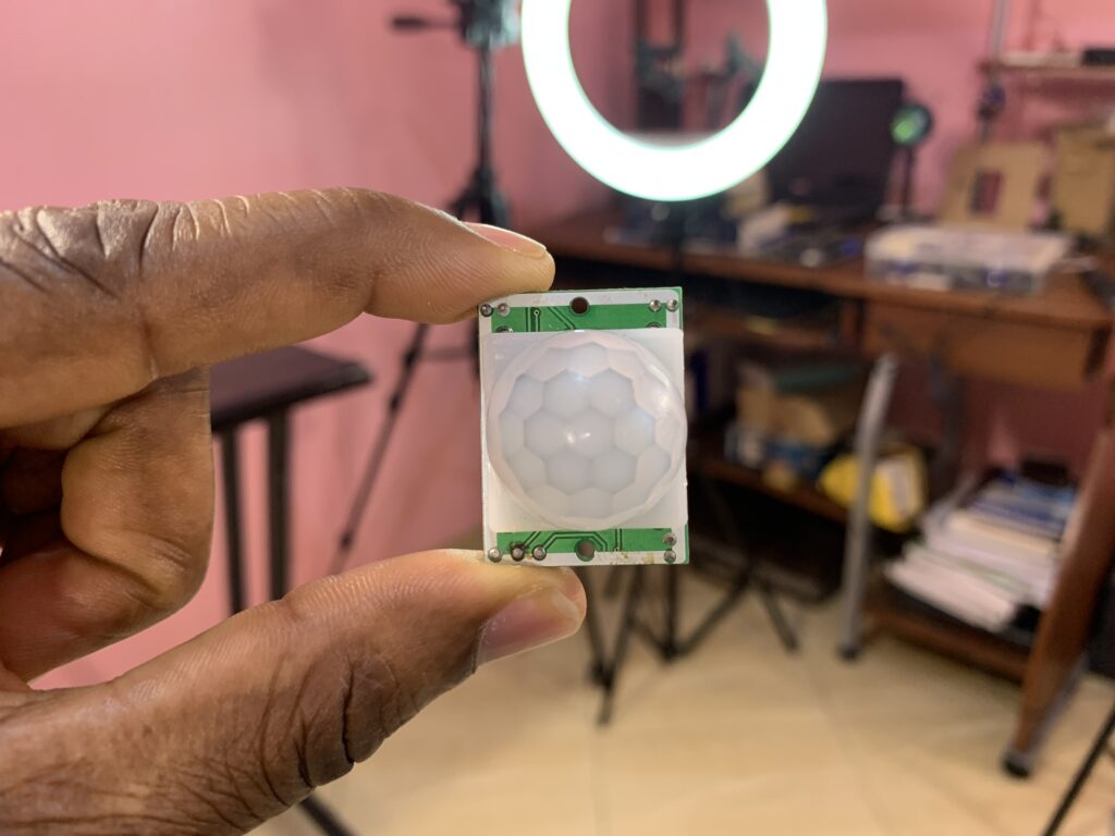
PIR sensor is a sensor module that was built to detect all living objects, such as humans and animals, whose body temperature is greater than 0°C. These objects emit the heat in the form of infrared radiation through their body, called thermal radiation.
The sensor does not generate or radiate any energy for detection purposes, making it a passive sensor.
Our sensor does not detect or measure heat, it’s rather detects the infrared radiation emitted or reflected by the objects.
PIR sensors are often found at home, hospitals, factories, etc, and they are small, inexpensive, low power, and easy to use.
PIR Sensor Specifications
- Sensitivity: Adjustable
- Output signal: 3.3V digital output
- Operating voltage: DC 4.5V-12V
- Detection angle: 110 degrees
- Detection range: up to 7 meters
- Delay time: adjustable from 0.4 seconds to 5 minutes
PIR sensor pinout
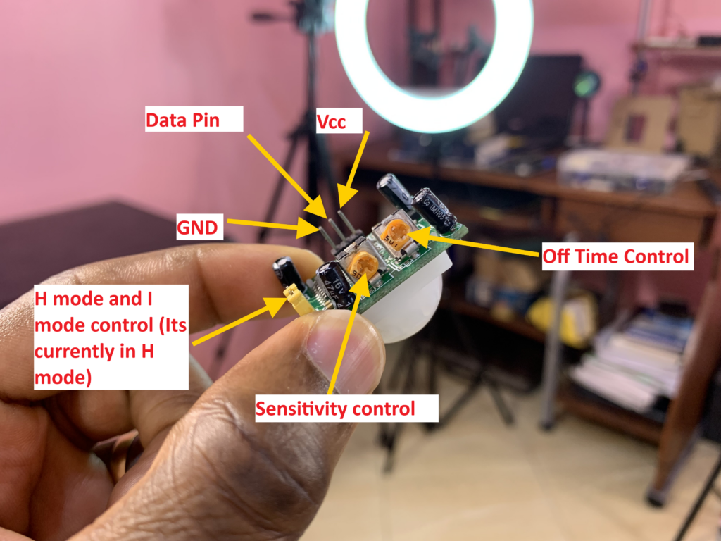
For more information about the PIR sensor:
https://www.electronicwings.com/sensors-modules/pir-sensor
I2C serial interface 1602 LCD module
I used in this project the 16×2 LCD Display to display messages depending on the state of the PIR sensor.
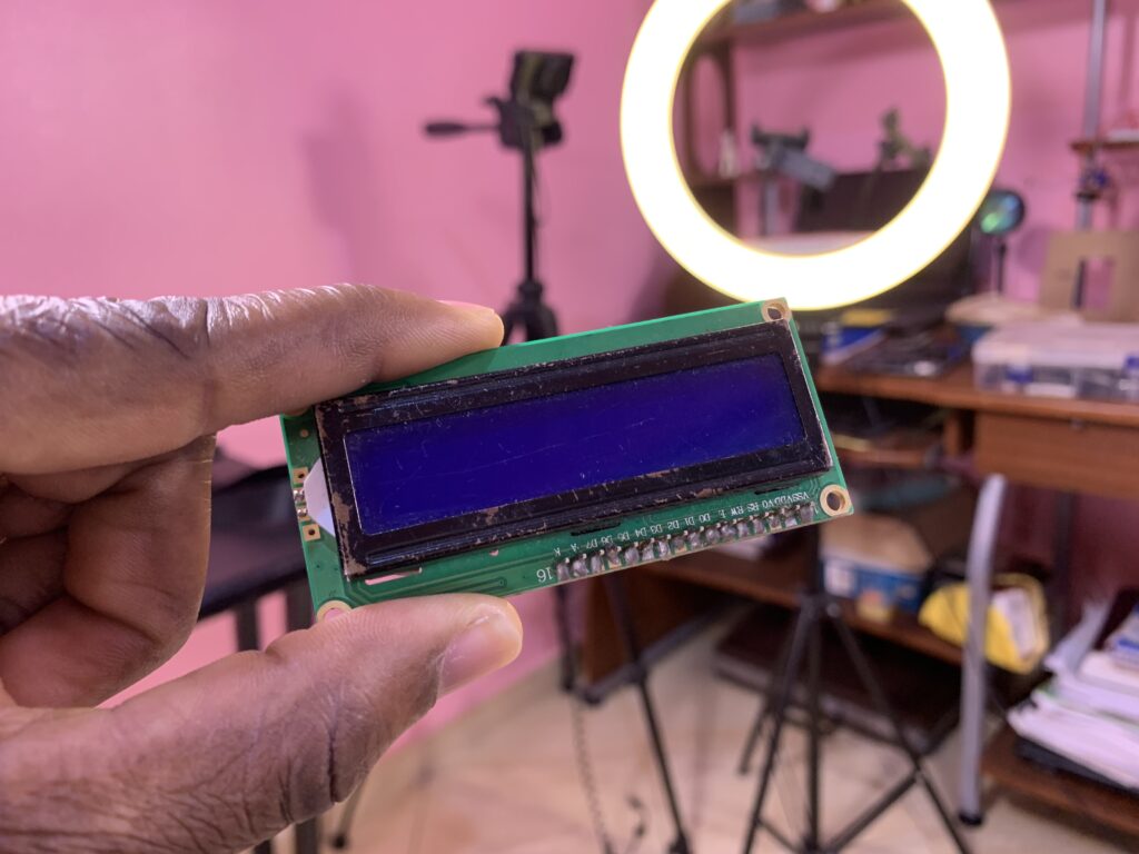
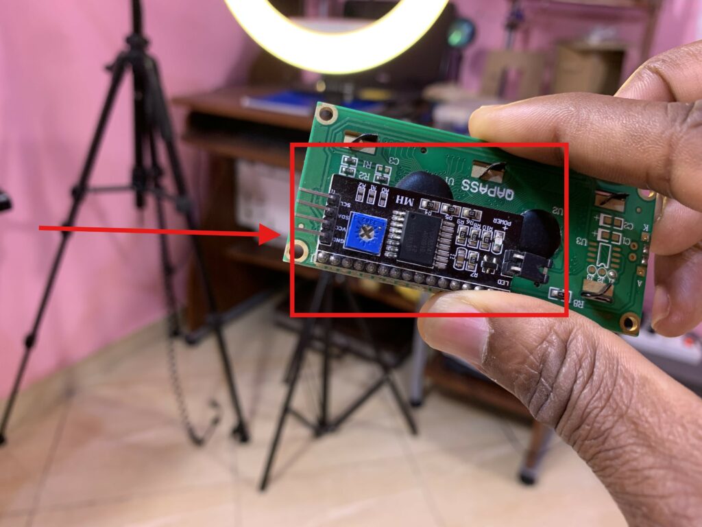
I soldered on the back of the 16×2 LCD module the I2C-to-LCD piggy-back board.
The I2C-to-LCD piggy-back board is a high-quality 2 lines 16 character LCD Module with an on-board contrast control adjustment, backlight, and I2C communication protocol. The I2C interface 16×2 LCD display module aims to eliminate the cumbersome and complex connection of LCD driver circuits. The goal of the I2C Serial LCD module is to simplify the circuit connection, save I/O pins on the Arduino board, and streamline firmware development with a widely available Arduino library.
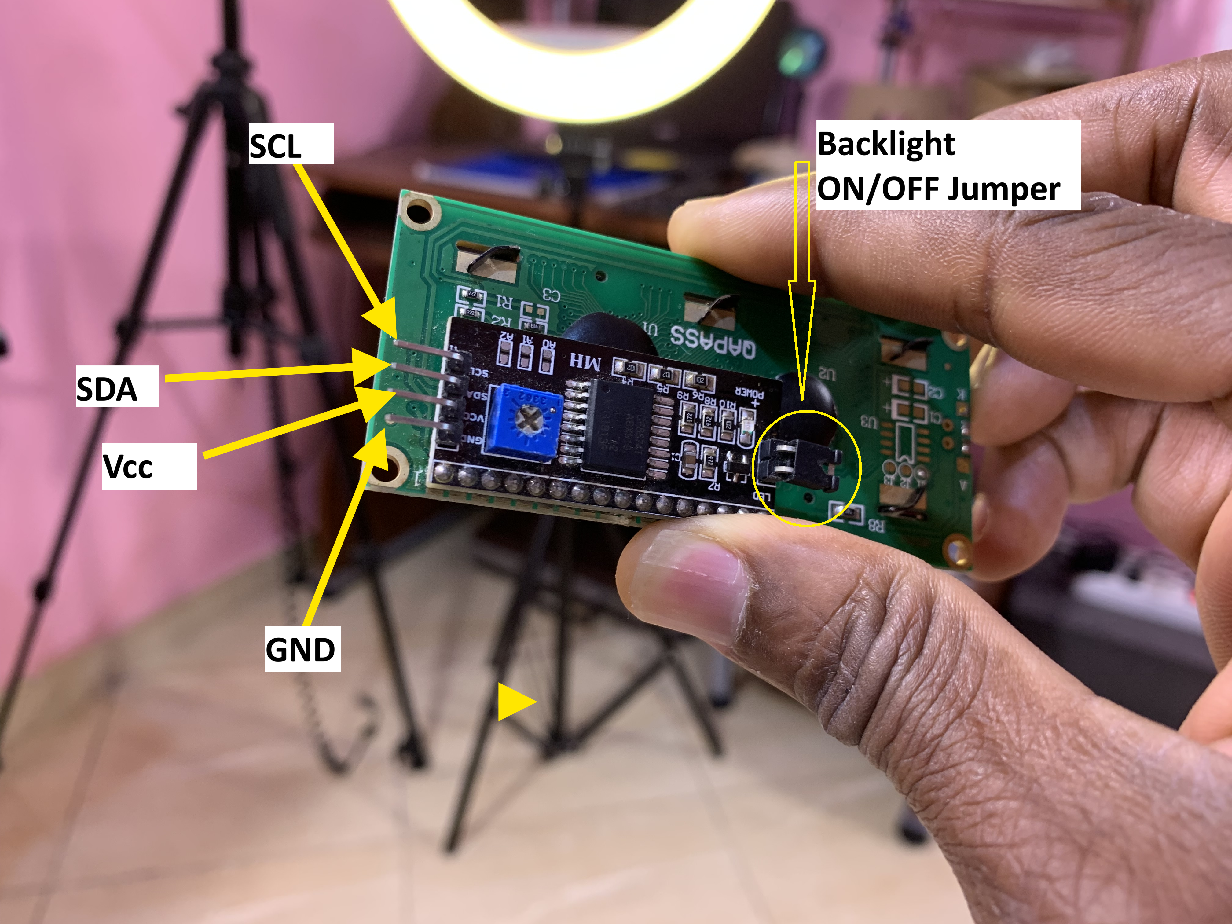
I2C Serial LCD module pinout and soldering
While soldering the I2C-to-LCD piggy-back board to the 16-pin LCD module, ensure that the I2C-to-LCD piggy-back board pins are straight and fit in the LCD module, then solder in the first leg while keeping the I2C-to-LCD piggy-back board in the same plane with the LCD module.
ESPNow Protocol Communication
According to ESpressif ESP-Now is a connectionless Wi-Fi protocol communication. In this protocol, the application data is encapsulated in a vendor-specific action frame and transmitted from one Wi-Fi device to another Wi-Fi device without a connection.
To transmit ESP-Now data, ESP-Now uses a vendor-specific action frame. 1Mbps is the default ESP-Now bit rate. CTR, along with CBC-MAC Protocol (CCMP) is used to protect the action frame for security.
In this project, I used the ESPnow protocol for wireless communication between the two ESP8266s. The PIR sensor was attached to the transmitter microcontroller, and the buzzer, LED, and LCD were attached to the receiver microcontroller.
ESP-Now protocol is widely used in remote control, sensor, smart light, etc.
For more information about the ESP-Now:
https://docs.espressif.com/projects/esp-idf/en/stable/esp32/api-reference/network/esp_now.html
MAC Address
In the ESP-Now protocol communication, the transmitter board must know the MAC address of the receiver board so that the transmitter board can send the data to the receiver microcontroller. We need to implement in the transmitter board Arduino code the MAC address of the receiver. Below is the Arduino code that allows you to know the receiver’s MAC address:
/*
 * GetMacAddress
 *
 * This sketch prints out the MAC addresses for different interfaces.
 *
 * Written by: Daniel Nebert
 *
 * The first printed MAC address is obtained by calling 'esp_efuse_mac_get_default'
 * (https://docs.espressif.com/projects/esp-idf/en/release-v5.1/esp32/api-reference/system/misc_system_api.html#_CPPv425esp_efuse_mac_get_defaultP7uint8_t)
 * which returns base MAC address which is factory-programmed by Espressif in EFUSE.
 *
 * The remaining printed MAC addresses is obtained by calling 'esp_read_mac'
 * (https://docs.espressif.com/projects/esp-idf/en/release-v5.1/esp32/api-reference/system/misc_system_api.html#_CPPv412esp_read_macP7uint8_t14esp_mac_type_t)
 * and passing in the 'esp_mac_type_t' type.
 * (https://docs.espressif.com/projects/esp-idf/en/release-v5.1/esp32/api-reference/system/misc_system_api.html#esp__mac_8h_1a1b19aca597277a2179682869c140477a)
 *

esp_mac_type_t values:

  ESP_MAC_WIFI_STA - MAC for WiFi Station (6 bytes)
  ESP_MAC_WIFI_SOFTAP - MAC for WiFi Soft-AP (6 bytes)
  ESP_MAC_BT - MAC for Bluetooth (6 bytes)
  ESP_MAC_ETH - MAC for Ethernet (6 bytes)
  ESP_MAC_IEEE802154 - if CONFIG_SOC_IEEE802154_SUPPORTED=y, MAC for IEEE802154 (8 bytes)
  ESP_MAC_BASE - Base MAC for that used for other MAC types (6 bytes)
  ESP_MAC_EFUSE_FACTORY - MAC_FACTORY eFuse which was burned by Espressif in production (6 bytes)
  ESP_MAC_EFUSE_CUSTOM - MAC_CUSTOM eFuse which was can be burned by customer (6 bytes)
  ESP_MAC_EFUSE_EXT - if CONFIG_SOC_IEEE802154_SUPPORTED=y, MAC_EXT eFuse which is used as an extender for IEEE802154 MAC (2 bytes)

*/

#include "esp_mac.h" // required - exposes esp_mac_type_t values

void setup() {

  Serial.begin(115200);
  while(!Serial) { delay( 100 ); }

  Serial.println("Interface\t\t\t\t\t\tMAC address (6 bytes, 4 universally administered, default)");

  Serial.print("Wi-Fi Station (using 'esp_efuse_mac_get_default')\t");
  Serial.println(getDefaultMacAddress());

  Serial.print("WiFi Station (using 'esp_read_mac')\t\t\t");
  Serial.println(getInterfaceMacAddress(ESP_MAC_WIFI_STA));

  Serial.print("WiFi Soft-AP (using 'esp_read_mac')\t\t\t");
  Serial.println(getInterfaceMacAddress(ESP_MAC_WIFI_SOFTAP));

  Serial.print("Bluetooth (using 'esp_read_mac')\t\t\t");
  Serial.println(getInterfaceMacAddress(ESP_MAC_BT));

  Serial.print("Ethernet (using 'esp_read_mac')\t\t\t\t");
  Serial.println(getInterfaceMacAddress(ESP_MAC_ETH));
}

void loop() { /* Nothing in loop */ }

String getDefaultMacAddress() {

  String mac = "";

  unsigned char mac_base[6] = {0};

  if(esp_efuse_mac_get_default(mac_base) == ESP_OK) {
    char buffer[18]; // 6*2 characters for hex + 5 characters for colons + 1 character for null terminator
    sprintf(buffer, "%02X:%02X:%02X:%02X:%02X:%02X", mac_base[0], mac_base[1], mac_base[2], mac_base[3], mac_base[4], mac_base[5]);
    mac = buffer;
  }

  return mac;
}

String getInterfaceMacAddress(esp_mac_type_t interface) {

  String mac = "";

  unsigned char mac_base[6] = {0};

  if(esp_read_mac(mac_base, interface) == ESP_OK) {
    char buffer[18]; // 6*2 characters for hex + 5 characters for colons + 1 character for null terminator
    sprintf(buffer, "%02X:%02X:%02X:%02X:%02X:%02X", mac_base[0], mac_base[1], mac_base[2], mac_base[3], mac_base[4], mac_base[5]);
    mac = buffer;
  }

  return mac;
}
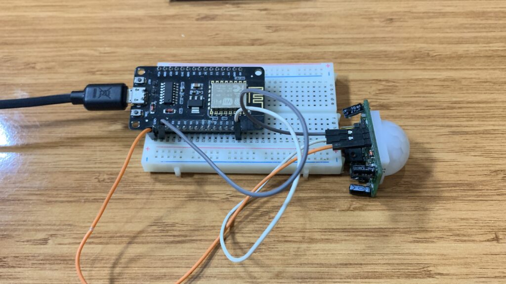
Transmitter circuit
Transmitter code
#include <ESP8266WiFi.h>
#include <espnow.h>
const int pIRsensor = D0;
// REPLACE WITH YOUR RECEIVER MAC Address 58:bf:25:da:c9:c8 MAC: 58:bf:25:da:c9:c8
uint8_t broadcastAddress[] = {0x58, 0xBF, 0x25, 0xDA, 0xC9, 0xC8};
typedef struct struct_message {
int state ;
} struct_message;
// Create a struct_message called myData
struct_message myData;
//esp_now_peer_info_t peerInfo;
// callback when data is sent - I CAN CHANGE THIS FUNCTION BELOW
// Callback when data is sent
void OnDataSent(uint8_t *mac_addr, uint8_t sendStatus) {
Serial.print("Last Packet Send Status: ");
if (sendStatus == 0){
Serial.println("Delivery success");
}
else{
Serial.println("Delivery fail");
}
}
void setup() {
// Init Serial Monitor
Serial.begin(115200);
// Set device as a Wi-Fi Station
WiFi.mode(WIFI_STA);
// Init ESP-NOW
if (esp_now_init() != 0) {
Serial.println("Error initializing ESP-NOW");
return;
}
pinMode(pIRsensor, INPUT);
// Once ESPNow is successfully Init, we will register for Send CB to
// get the status of Trasnmitted packet
esp_now_set_self_role(ESP_NOW_ROLE_CONTROLLER);
esp_now_register_send_cb(OnDataSent);
// Register peer
esp_now_add_peer(broadcastAddress, ESP_NOW_ROLE_SLAVE, 1, NULL, 0);
}
void loop() {
myData.state = digitalRead(pIRsensor);
esp_now_send(broadcastAddress, (uint8_t *) &myData, sizeof(myData));
Serial.println( myData.state);
delay(30);
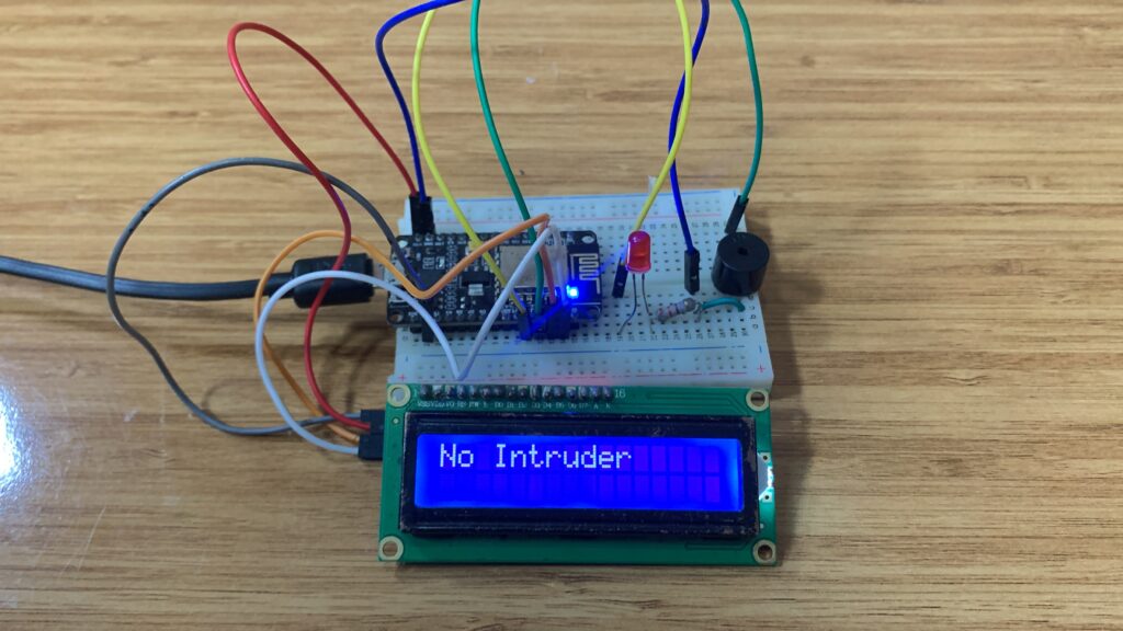
}Receiver circuit
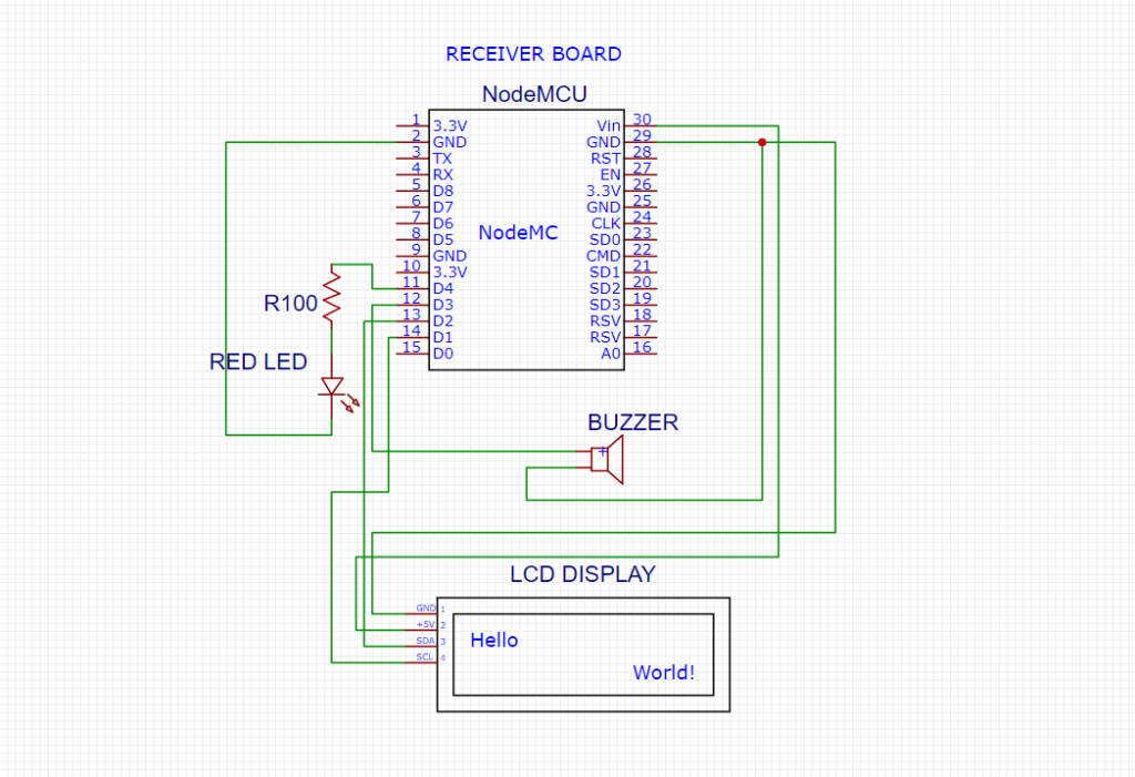
Receiver code
#include <ESP8266WiFi.h>
#include <espnow.h>
#include <Wire.h>
#include <LiquidCrystal_I2C.h>

const int lightME = D3;
const int buzzer = D4;

// Initialize LCD: 0x27 is a common I2C address. Adjust if needed.
LiquidCrystal_I2C lcd(0x27, 16, 2);

typedef struct struct_message {
  int state;
} struct_message;

struct_message myData;

String lastMessage = "";  // To prevent redundant LCD refresh

// Function to display messages only when content changes
void displayMessage(const String& message) {
  if (message != lastMessage) {
    lcd.clear();
    lcd.setCursor(0, 0);
    lcd.print(message);
    lastMessage = message;
  }
}

// Callback function when data is received
void OnDataRecv(uint8_t * mac, uint8_t *incomingData, uint8_t len) {
  memcpy(&myData, incomingData, sizeof(myData));

  Serial.print("PIR Sensor: ");
  Serial.println(myData.state);

  // Control buzzer and LED
  digitalWrite(lightME, myData.state);
  digitalWrite(buzzer, myData.state);

  // Display message on LCD
  if (myData.state == 1) {
    displayMessage("Intruder Detect..");
  } else {
    displayMessage("No Intruder");
  }
}

void setup() {
  pinMode(lightME, OUTPUT);
  pinMode(buzzer, OUTPUT);

  Serial.begin(115200);

  // Initialize LCD
  lcd.init();
  lcd.backlight();
  displayMessage("Waiting Data...");

  WiFi.mode(WIFI_STA);

  if (esp_now_init() != 0) {
    Serial.println("Error initializing ESP-NOW");
    return;
  }

  esp_now_set_self_role(ESP_NOW_ROLE_SLAVE);
  esp_now_register_recv_cb(OnDataRecv);
}

void loop() {
  // Nothing here
}
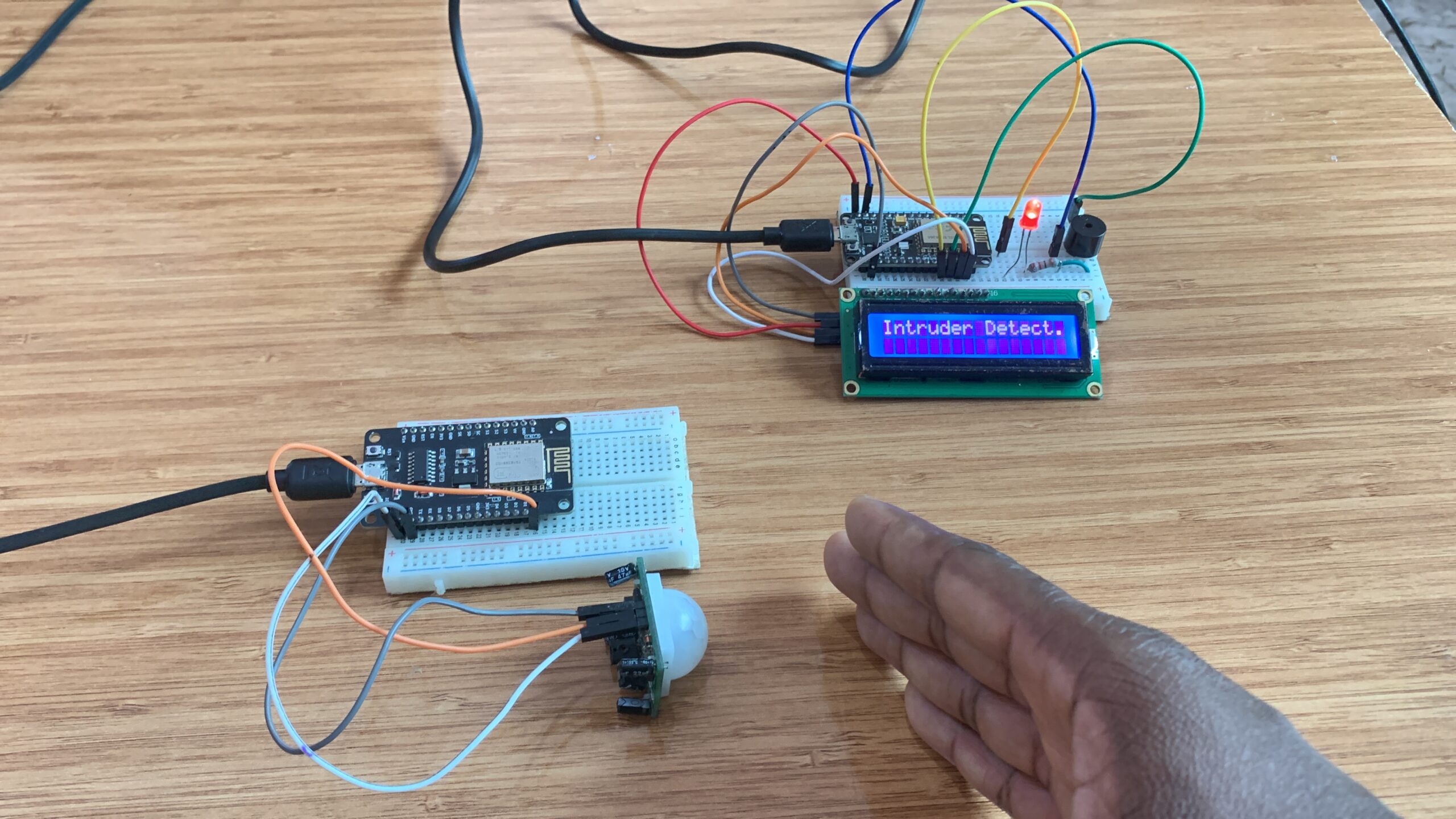
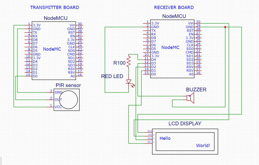
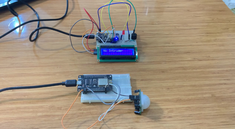
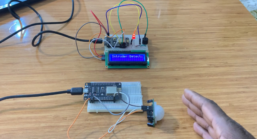
Transmitter and receiver circuit
How the project works
The transmitter constantly reads the PIR sensor on pin D0 to detect movement.
Each time motion is detected, it sends the sensor state (1 or 0) wirelessly via ESP-NOW.
This data is transmitted directly to the receiver using the saved MAC address.
The receiver gets the data through ESP-NOW and activates the LED and buzzer whenever the
value is “1”.
At the same time, the LCD shows “Intruder Detect..” or “No Intruder” depending on the sensor
state.
This creates a wireless motion-alert system without Wi-Fi or an internet connection.
Bonjour,
j’aimerais savoir car je n’ai pas aperçu cette info, jusqu’à quelle est la distance maxi peut on avoir entre émetteur et récepteur?
Bravo, pour votre site qui m’aide beaucoup dans mes réalisations et d’apprentissage sur Arduino.
Cdlt
Jacques
Je pense que nous pouvons atteindre plus de 500 mètres avec ESP-NOW.