Rain Detection with Arduino: Servo Control, LED Alert, and LED Matrix Display
In this tutorial, you are about to learn to control the door lock with Arduino Uno R4 WI-FI and the raindrops module.
Before moving on, make sure you have the Arduino IDE installed on your laptop, and you have the Arduino IDE because we gonna be scroll a message on the LED matrix.

Parts required
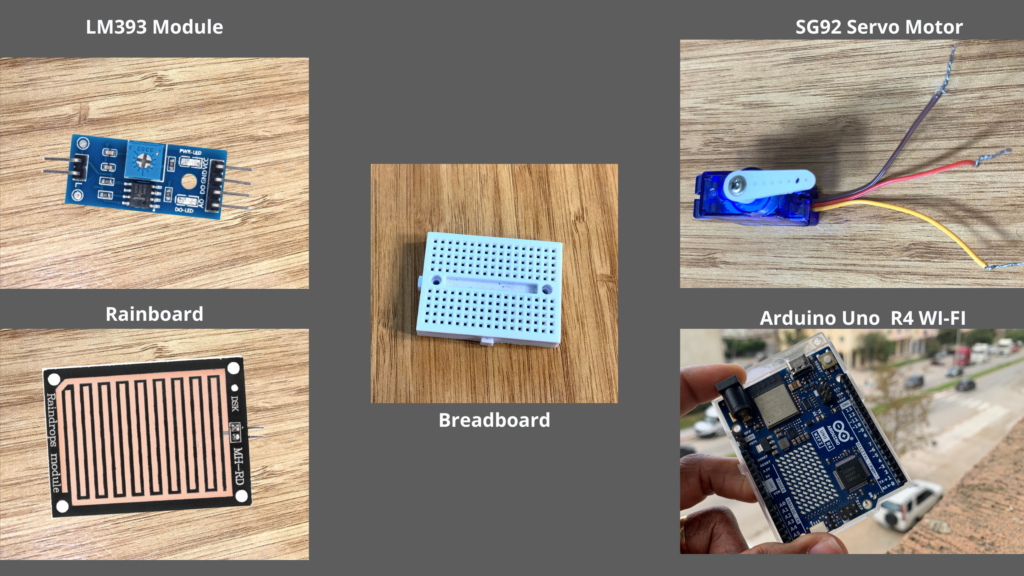
- Arduino Uno R4 WI-FI
- Raindrops Module
- SG90R Servo Motor
- Breadboard(optional)
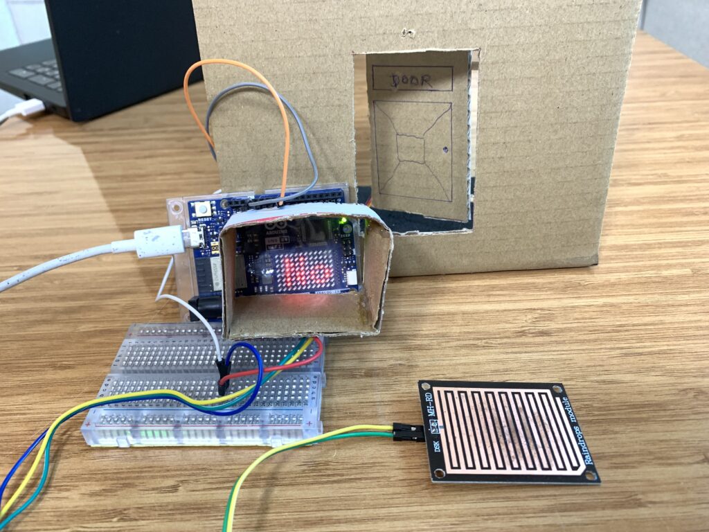
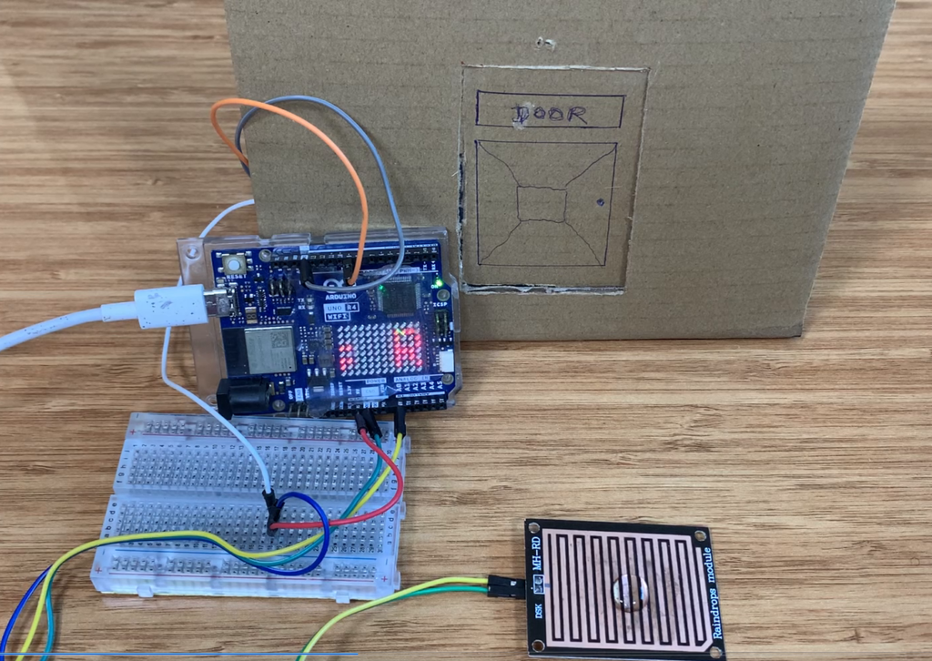
The door we gonna be opening i made out of cardboard, since i don’t have a 3D printer. Like on a wall, I draw on the cardboard to make the door. I drew the shape of the door using a pen and rule, of course, then made the necessary cuts with a sharp knife to create a door that can open and close using the SG92R and raindrops module.
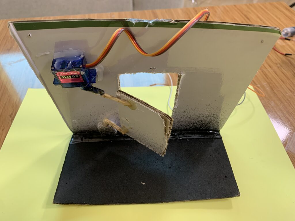
Behind the door, I created a mechanical system to control the movement of the door. Using hot glue, I attached two small sticks, then glued them to the rotating plastic arm of the SG92R servo motor.
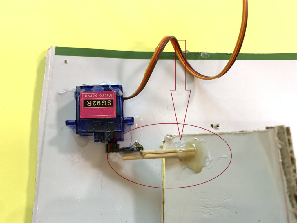
On the top-left side of the door, behind it, I fixed the servo motor. The other ends of the two glued sticks were connected to the top-left corner of the door, allowing it to move when the servo motor rotates to open and close the door.
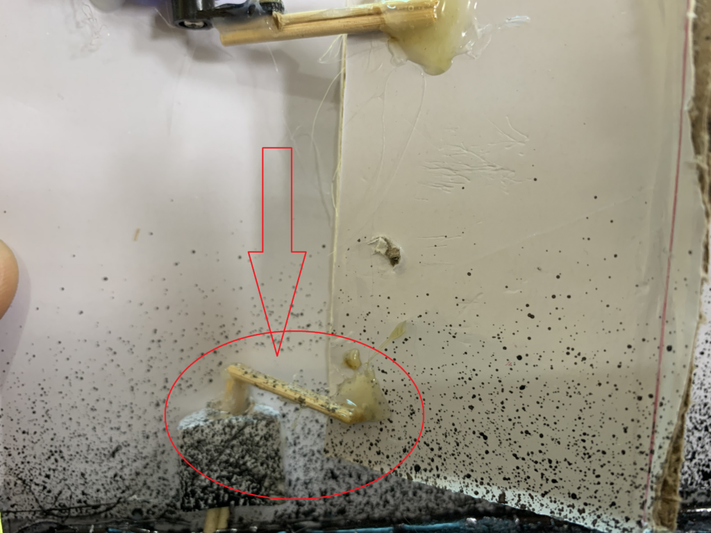
I got another pair of sticks, glued them together, and connected them to a simple linkage mechanism(made out of cardboard) at the bottom-left corner of the door.
Raindrops Module.
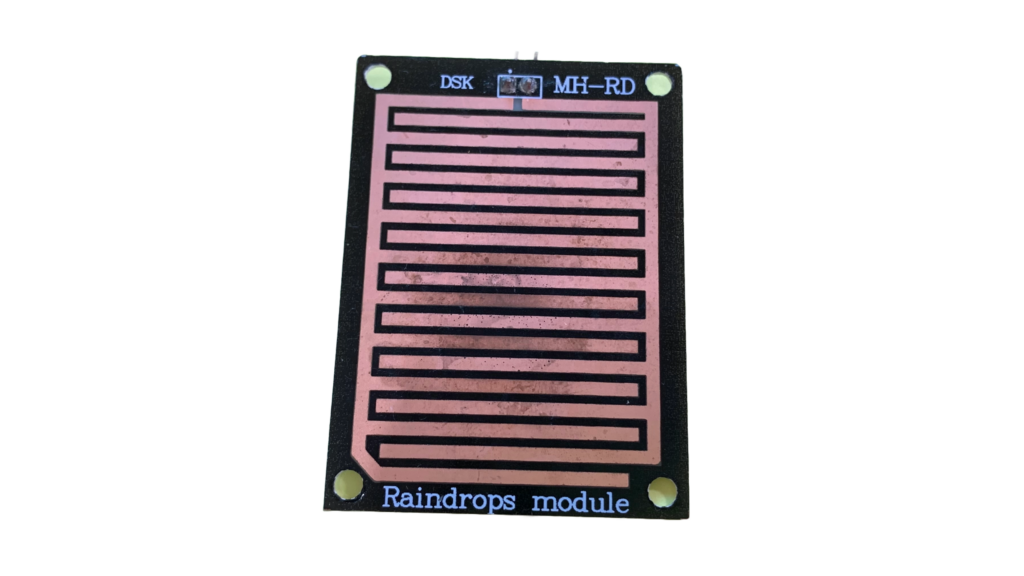
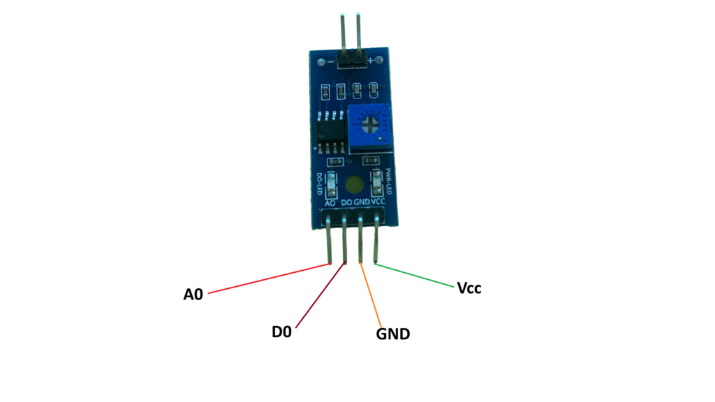
The Raindrops sensor is a module used in a rain detection project, and it can also measure the intensity of rainfall. The raindrops module includes a rainboard that collects water and a control board, which is based on the LM393 IC. The control features a built-in LED used as a power indicator and a potentiometer for adjusting the sensor’s sensitivity.
Paths of parallel resistance are created as raindrops are collected on the printed circuit board; these paths of parallel resistance are measured via the op amp.
Specifications of the raindrops module
- Power supply: 5V
- Data signal: digital and analog output
- Adjustable sensitivity
- LED indicator for Output
- TTL compatible
- Bolt holes for easy installation
Print circuit board
LM393 Module
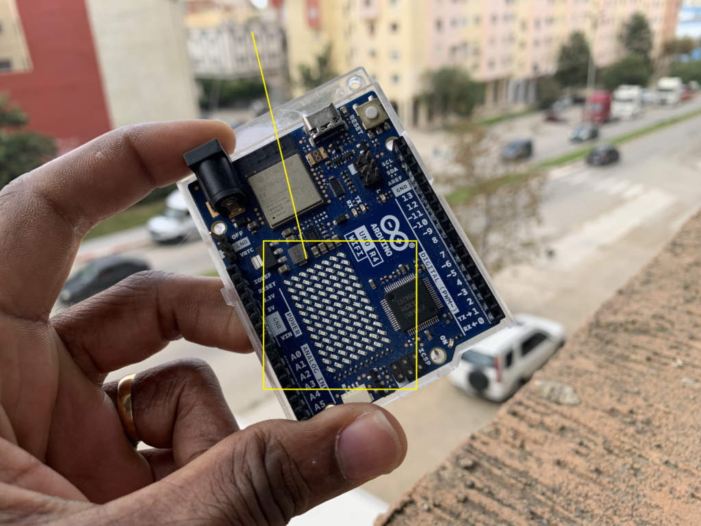
Arduino Uno R4 WI-FI LED Matrix
In this project, we are going to scroll a message from right to left on the Arduino Uno R4 WI-FI LED matrix. This is a 12X8 LED matrix that makes it possible to prototype visuals directly on the Arduino board. If you have a Qwiic connector, you can create projects plug-and-play style.
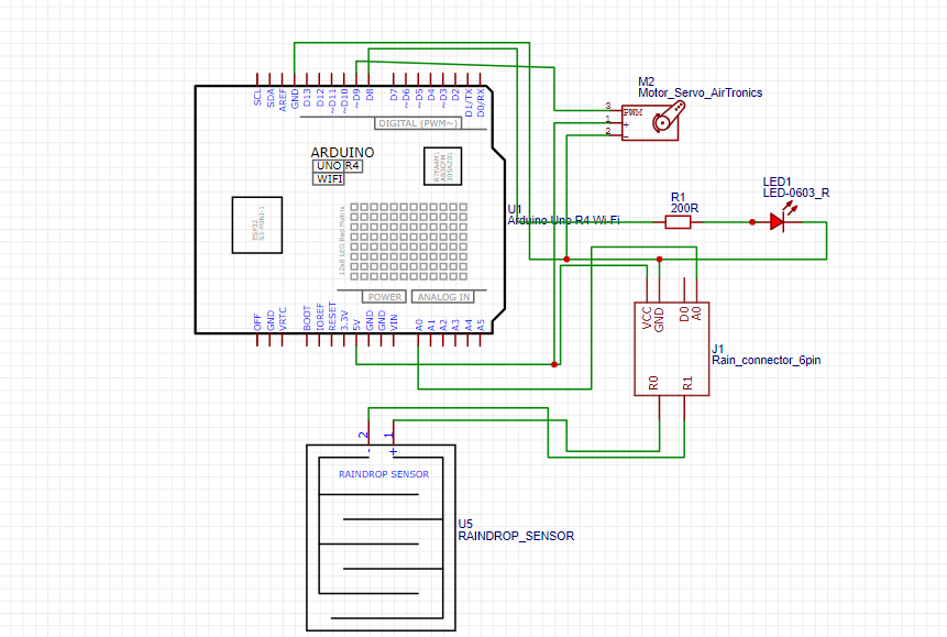
Circuit Diagram
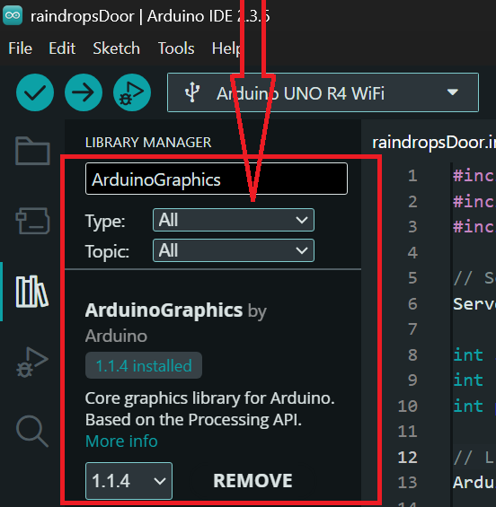
Install the ArduinoGraphics library
Make sure to install the ArduinoGraphics library, so open the Arduino IDE and click on library manager.
In the search bar, type “ArduinoGraphics” and look for the library named “ArduinoGraphics by Arduino”
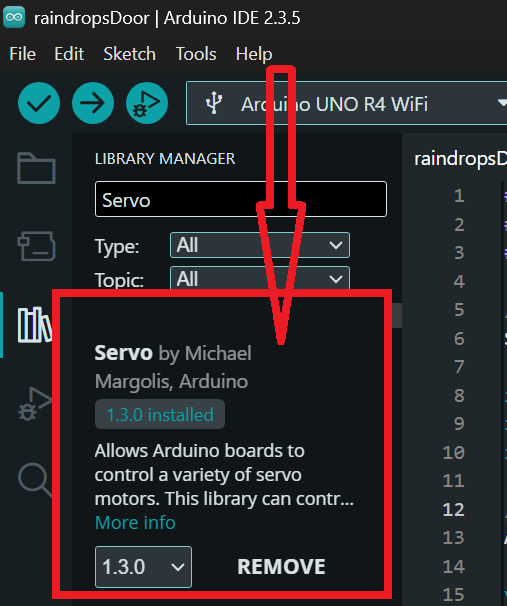
Install the Servo library
Make sure to install the Servo library to send and receive from RFID cards and key fobs electromagnetic waves at 13.56 million cycles per second.
In the search bar, type “Servo” and look for the library named “Servo by Michael Margolis, Arduino”.
Arduino code
#include <Servo.h>
#include <ArduinoGraphics.h>
#include "Arduino_LED_Matrix.h"

// Servo setup
Servo myservo1;

int servoPin1 = 9;       // Servo signal pin
int raindrops = A0;      // Analog pin for raindrop sensor
int pinLED = 7;          // LED pin

// LED Matrix object
ArduinoLEDMatrix matrix;

void setup() {

  // Servo
  myservo1.attach(servoPin1);
  myservo1.write(0);

  pinMode(raindrops, INPUT);
  pinMode(pinLED, OUTPUT);

  Serial.begin(115200);

  // LED MATRIX
  matrix.begin();
  matrix.textScrollSpeed(300);
  matrix.textFont(Font_5x7);
}

void loop() {

  int analogdropsvalue = analogRead(raindrops);
  Serial.println(analogdropsvalue);
  delay(2);

  // Start drawing on LED matrix
  matrix.beginDraw();
  matrix.beginText(2, 1, 0xFFFFFF);  // white text

  if (analogdropsvalue < 750) {
    // RAIN DETECTED
    myservo1.write(27);
    digitalWrite(pinLED, HIGH);

    matrix.println("It's Raining");
  }
  else {
    // NO RAIN
    myservo1.write(80);
    digitalWrite(pinLED, LOW);

    matrix.println("No rain");
  }

  matrix.endText(SCROLL_LEFT);   // scroll message
  matrix.endDraw();

  delay(300);   // scrolling frequency
}
How the project works
The Arduino reads the raindrop sensor value from the analog pin. If the sensor value becomes lower than 750, the Arduino understands that rain is detected. When rain is detected, the servo rotates to 27 degrees to move a mechanical part, and the LED turns ON.
At the same time, the LED matrix displays the message “It’s Raining” and scrolls it from right to left. If no rain is detected, the sensor value stays above 750. In this case, the servo rotates to 80 degrees, the LED turns OFF, and the LED matrix shows the message “No rain”.
The display scrolls the message continuously while the sensor keeps updating. The Serial Monitor prints the sensor values so you can see what the raindrop sensor is detecting in real time. The delay of 300 ms controls how fast the text scrolls on the LED matrix.
Veuillez envoyer Un fichier PDF
Je ne comprend pas, le cours en pdf?