Explaining the Arduino Code for the Rain-Controlled Door Lock Project
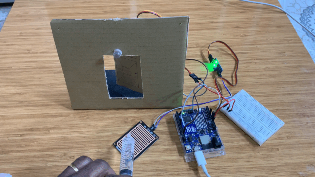
In this blog, I’ll show you how to control a door lock using the Arduino Uno R4 WiFi, a Raindrops sensor module, and a servo motor. You’ll learn about all the components used in this project and how to connect them to the Arduino board. Before getting started, make sure you have the Arduino IDE installed on your computer.
Raindrops Sensor Module
The Raindrops module is a sensor that detects rainfall. It consists of two main parts:
- A rain board, which senses the presence of rain.
- A control module that includes the LM393 comparator, which receives the analog signal from the rain board, compares it, and converts it into a digital signal.
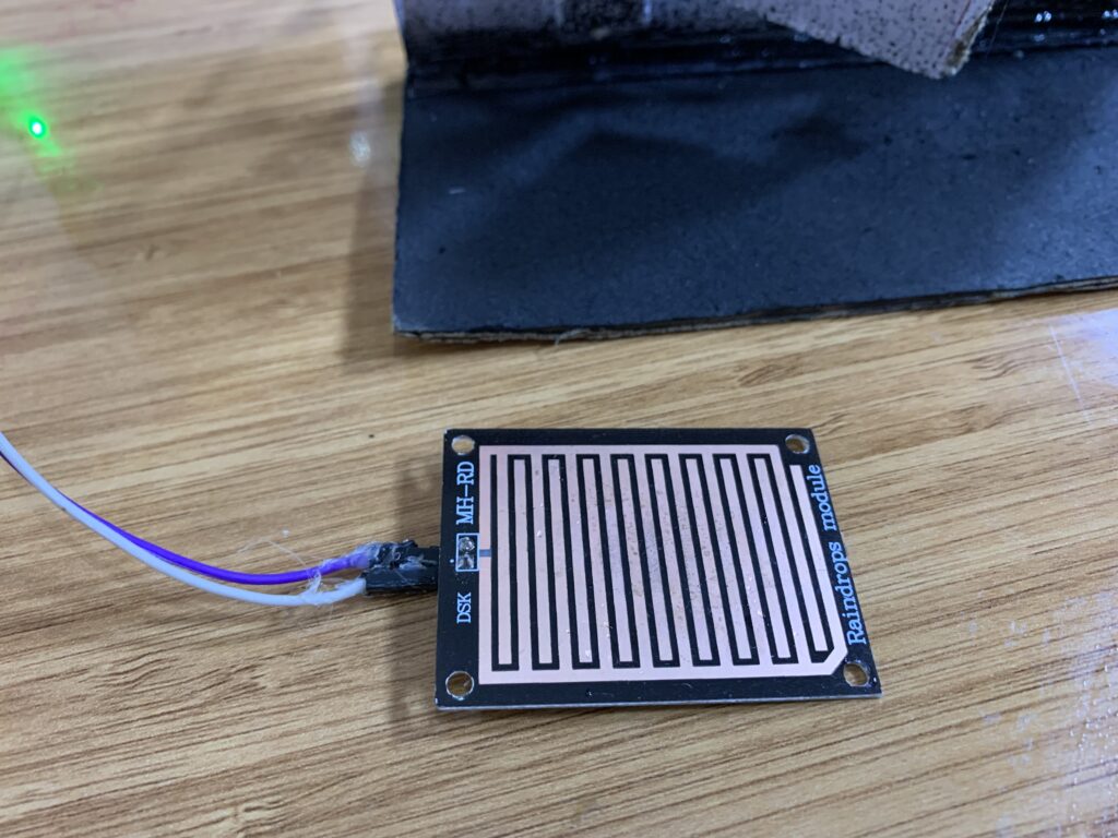
The Raindrops sensor has four pins:
- VCC – Power supply (usually 3.3V or 5V)
- GND – Ground connection
- D0 – Digital output
- A0 – Analog output
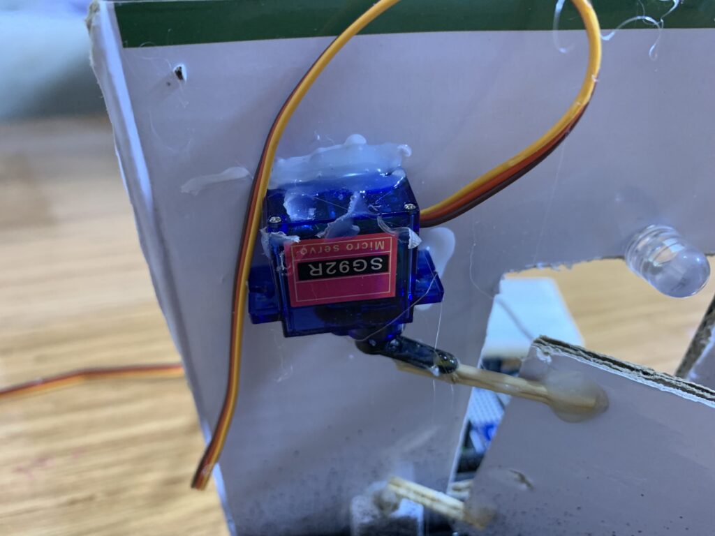
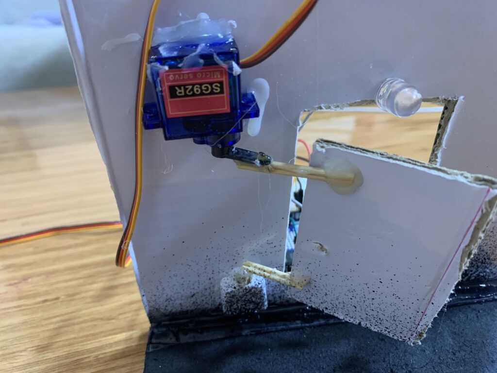
SG92R Servo Motor
In this project, I used the SG92R micro servo motor, a small and lightweight motor that operates at 5V. It provides a torque of 2.5 kg/cm and has a rotation range from 0° to 180°, making it ideal for precise control applications such as opening and closing a door lock.
White LED
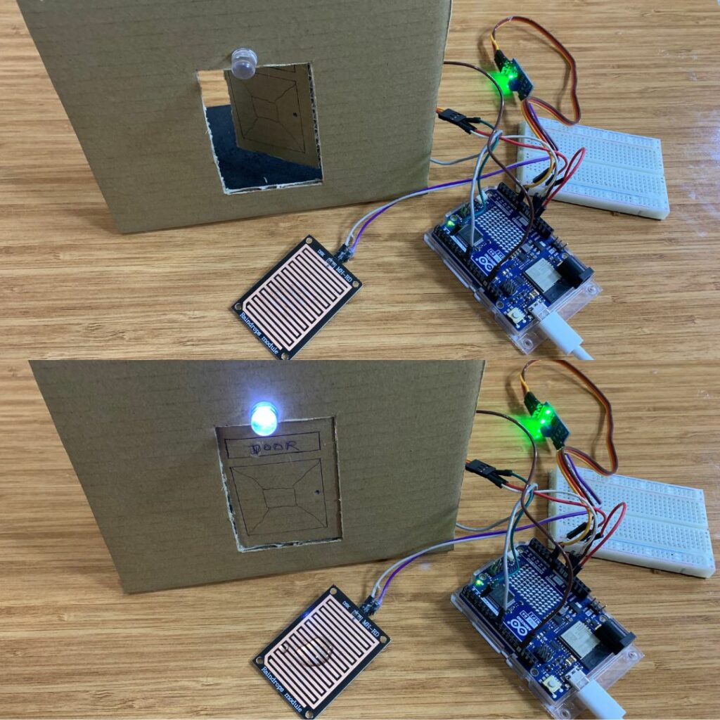
I used a large white LED that turns ON when the door closes and OFF when the door opens.
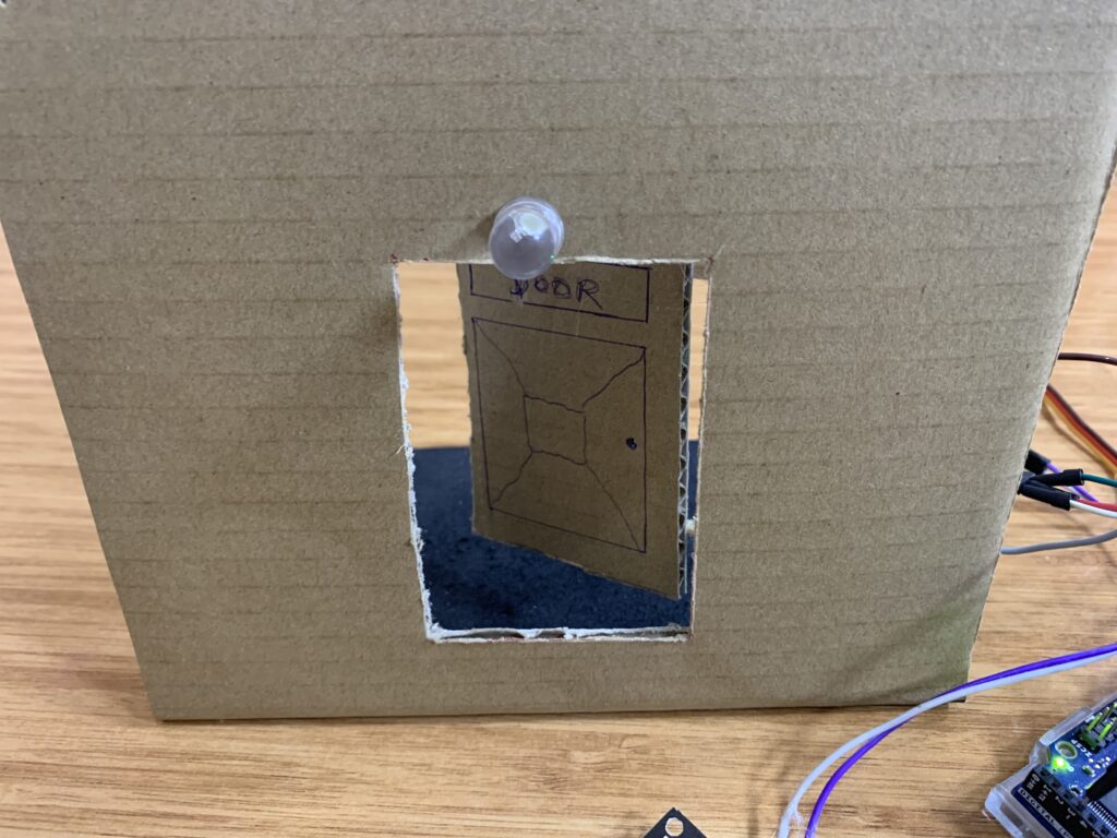
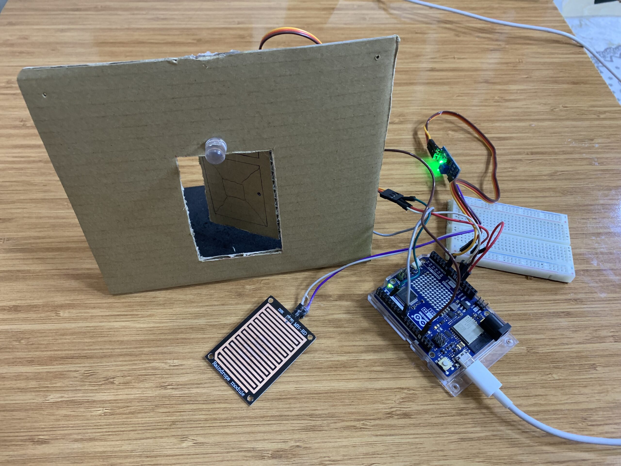
How I Built the Door
For this project, I used cardboard to create a small model of a door. On the back side, I mounted the servo motor at the bottom so it could open and close the door. On the front, I placed a large white LED above the door — just like a light above a real house entrance.
Parts Used in the Project
- Arduino Uno R4 WiFi (you can use another compatible Arduino board)
- Raindrops Sensor Module
- SG92R Servo Motor
- White LED (you can add a resistor in series to protect the LED)
- Breadboard
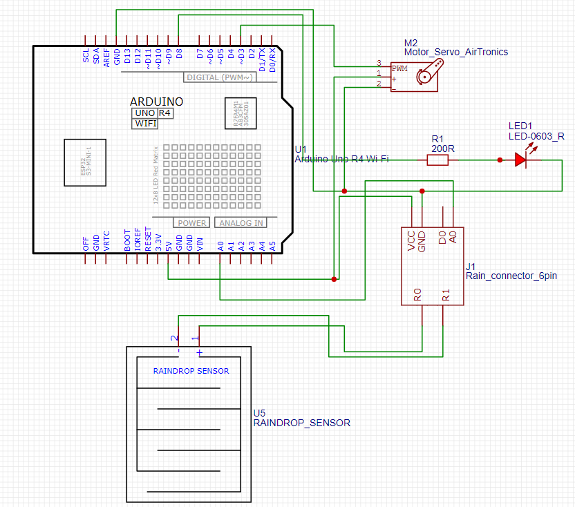
Circuit Diagram
Arduino Code
#include <Servo.h>

Servo myservo1; // create a servo object

int servoPin1 = 3;     // pin for servo
int raindrops = A0;    // analog pin for rain sensor
int pinLED = 8;        // digital pin for LED

void setup() {
  myservo1.attach(servoPin1);  // attach servo to pin
  myservo1.write(0);           // initial position

  pinMode(pinLED, OUTPUT);     // LED pin as output
  Serial.begin(115200);        // start serial monitor
  delay(1000);
  Serial.println("Rain Detection System Ready!");
}

void loop() {
  int analogdropsvalue = analogRead(raindrops);  // read analog value from rain sensor
  Serial.println(analogdropsvalue);
  delay(200);

  // If rain is detected (lower analog value = more water)
  if (analogdropsvalue < 950) {   // Arduino analogRead returns 0-1023
    myservo1.write(50);           // move servo to 50 degrees
    digitalWrite(pinLED, HIGH);   // turn LED ON
  } else {
    myservo1.write(90);           // move servo to 90 degrees
    digitalWrite(pinLED, LOW);    // turn LED OFF
  }
}
Code explanation
Includes the Servo library so you can control hobby servos (like the SG92R) using simple commands.
#include <Servo.h>
Declares a Servo object named myservo1. This object provides functions such as .attach() and .write() to control the servo.
Servo myservo1; // create a servo object
Creates an integer variable servoPin1 and sets it to digital pin 3. This is the Arduino pin you will connect the servo signal wire to.
int servoPin1 = 3; // pin for servo
Creates an integer raindrops set to analog pin A0. The raindrops module outputs an analog voltage proportional to the amount of water on the sensor; analogRead() will read it from this pin.
int raindrops = A0; // analog pin for rain sensor
Creates an integer pinLED set to digital pin 8. This pin controls the white LED (on = HIGH, off = LOW).
int pinLED = 8; // digital pin for LED
Start of the setup() function — this runs once when the Arduino boots or resets.
void setup() {
Tells the myservo1 object to use servoPin1 (pin 3). After this the servo library can send PWM pulses to control angle.
myservo1.attach(servoPin1); // attach servo to pin
Moves the servo to 0 degrees as the initial position. Good to set a defined starting state.
myservo1.write(0); // initial position
Configures pinLED (pin 8) as an OUTPUT so you can drive the LED with digitalWrite().
pinMode(pinLED, OUTPUT); // LED pin as output
Starts serial communication at 115200 baud so you can print values to the Serial Monitor for debugging or calibration.
Serial.begin(115200); // start serial monitor
Waits 1 second. This gives time for the servo and sensors to stabilize and for the Serial Monitor to open.
delay(1000);
Prints a startup message to the Serial Monitor so the user knows the program initialized.
Serial.println("Rain Detection System Ready!");
End of setup().
}
Start of loop() — runs repeatedly after setup().
void loop() {
Reads the analog voltage on A0, returning a value between 0 and 1023, and stores it in analogdropsvalue. Lower numbers indicate more water on the raindrops board (because water lowers the resistance/voltage).
int analogdropsvalue = analogRead(raindrops); // read analog value from rain sensor
Prints the raw analog sensor value to the Serial Monitor. Use this to watch changes and find a good threshold.
Serial.println(analogdropsvalue);
Short pause (200 ms) so the Serial Monitor output is readable and the loop doesn’t run too fast.
delay(200);
Checks whether the sensor reading is below 950. If it is, the code treats that as rain detected. (You can and should calibrate this threshold for your sensor and environment.)
  // If rain is detected (lower analog value = more water)
  if (analogdropsvalue < 950) {   // Arduino analogRead returns 0-1023
When rain is detected, move the servo to 50° (for example, this could open the door).
myservo1.write(50); // move servo to 50 degrees
Turn the LED on to indicate rain was detected (or to simulate an external light turning on).
digitalWrite(pinLED, HIGH); // turn LED ON
If the sensor reading is not below 950 (i.e., no rain detected) then do the following:
} else {
Move the servo to 90° (for example, this could be the closed door position).
myservo1.write(90); // move servo to 90 degrees
Turn the LED off.
digitalWrite(pinLED, LOW); // turn LED OFF
End of the if and the loop().
  }
}
How the project works
The Arduino reads the Raindrops sensor on analog pin A0 and compares the value to a threshold (950). When the reading is below 950 (water detected), the Arduino moves the SG92R servo to 50° to close the door and switches the LED ON. When the reading is 950 or higher (no water), the Arduino sets the servo to 90° to open the door and turns the LED OFF. You can adjust the threshold and servo angles to match your physical model.
[…] Arduino Uno R4 WiFi Rain Detection System […]