RFID-Controlled Cardboard House Door Using Arduino Uno R4 WiFi
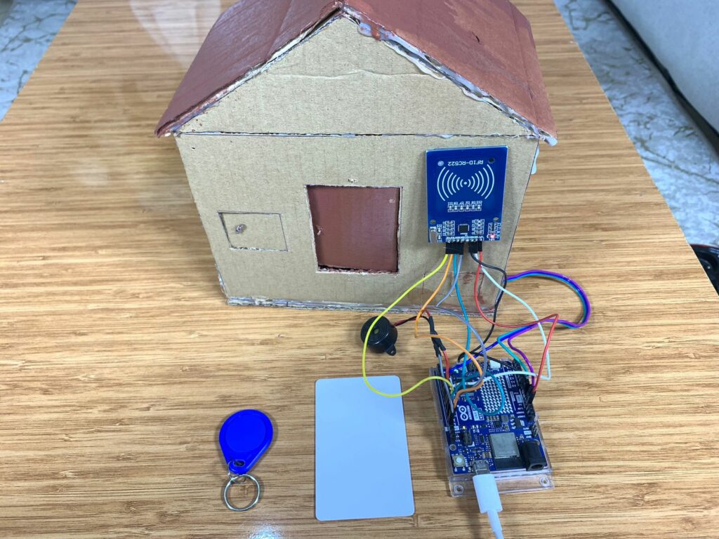
In this blog, you are going to learn how to build a house from cardboard and control its door automatically using the Arduino Uno R4 WiFi and the RC522 RFID Reader module.
I’ll show the necessary steps to make the project, as well as the components used.
Make sure you have the Arduino IDE installed on your machine before we get started.
Description
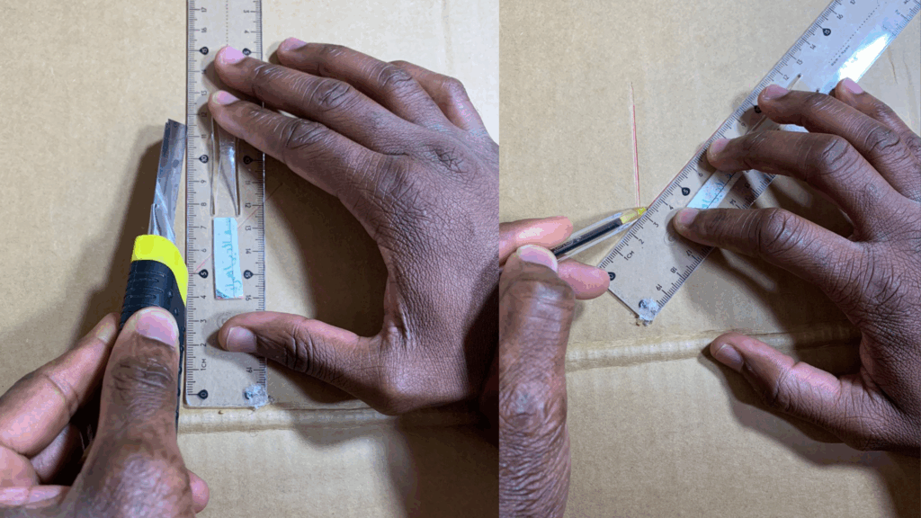
To build the house, I had to use cardboard since I didn’t buy a 3D printer machine. The most important part of the house is the door. While building it, I drew the shape of the door with a pen, of course, then I made the necessary cuts with a sharp knife to create a door that can open and close using the RC522 RFID and a tiny servo motor, SG90.
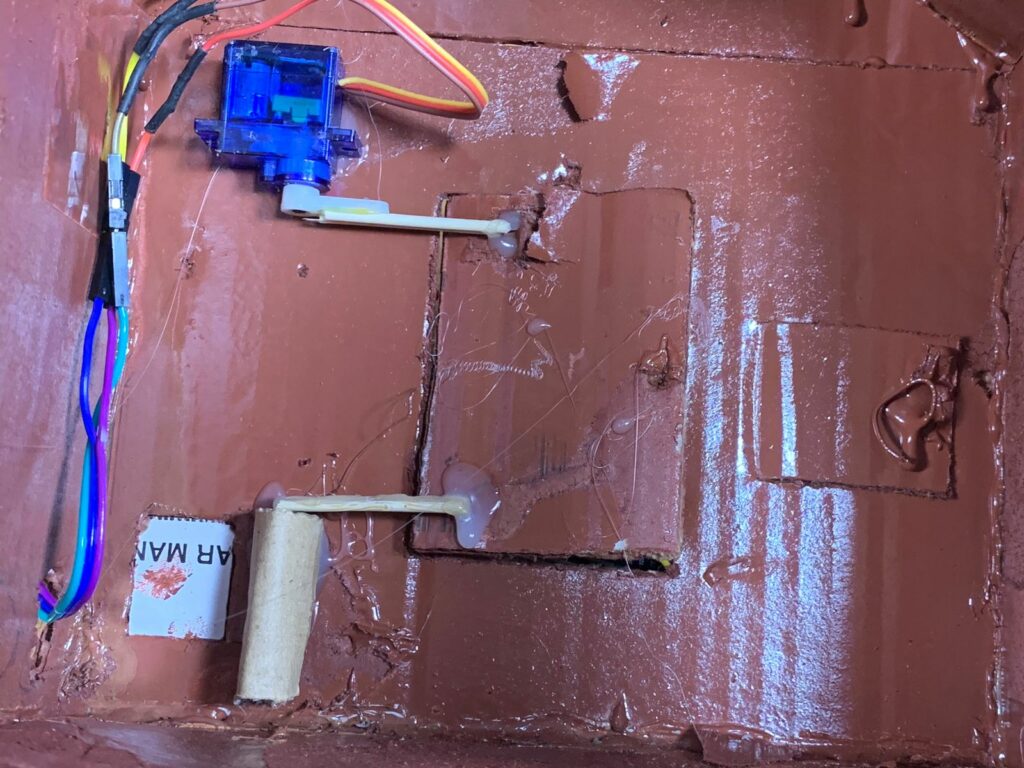
I invented a mechanical system to control the movement of the door. I used a hot-glue machine and attached two small sticks together, then glued them to the rotating plastic arm of the SG90 servo motor.
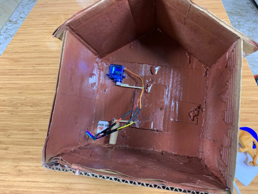
On the top-left side of the door, behind it, I fixed the servo motor. The free ends of the two glued sticks were connected to the top-left corner of the door, allowing it to move when the servo motor rotates to open and close the door.
I got another pair of sticks, glued them together, and connected them to a simple linkage mechanism(made out of cardboard) at the bottom-left corner of the door.
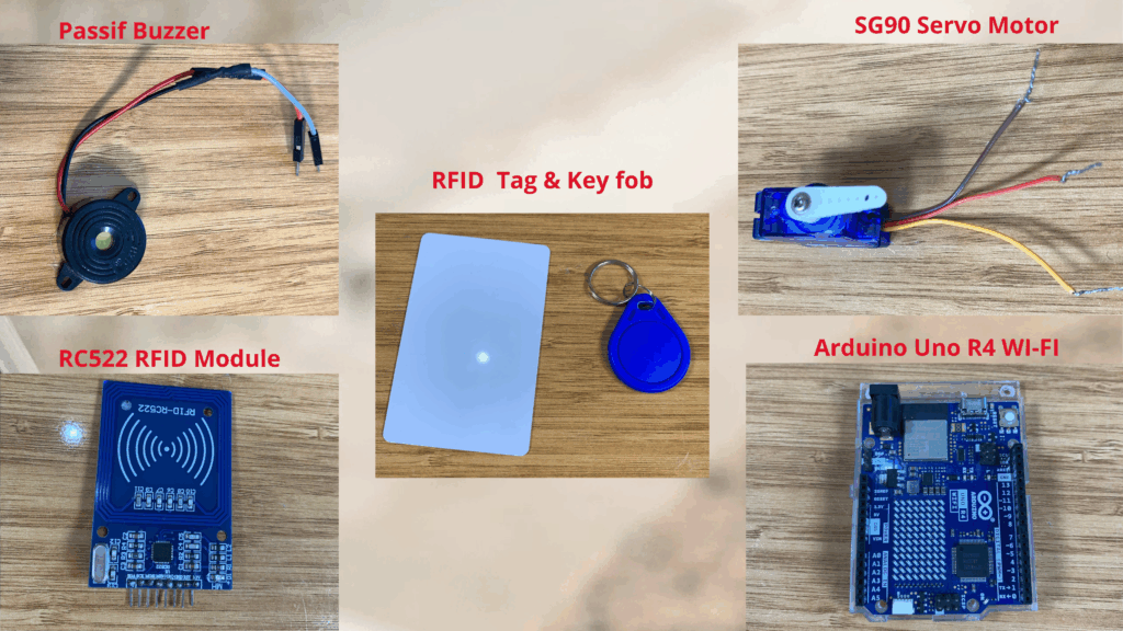
Electronic components used
- Arduino Uno R4 WiFi
- RC522 RFID Module
- SG90 Servo Motor
(You can also use another servo type) - Passive Buzzer
Servo Motor Pinout
The SG90 servo motor that I’m using is a very tiny servo motor, and it has three cables:
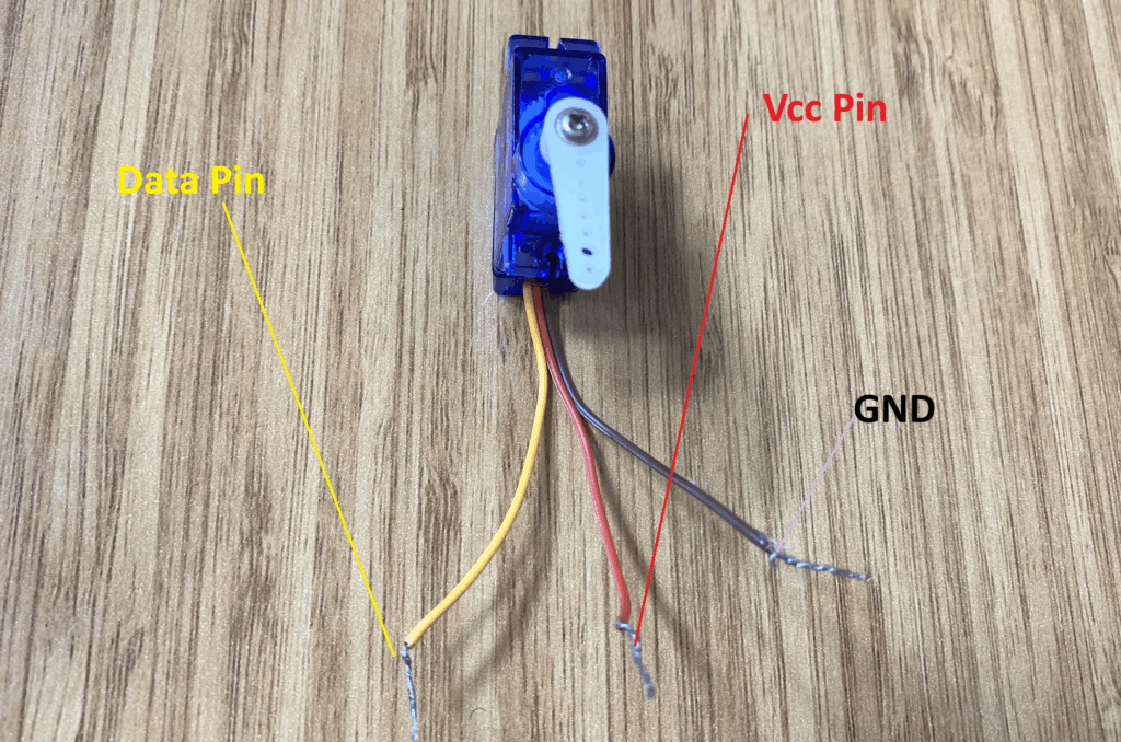
1- VCC pin (red cable)
2- Data pin (yellow cable)
3- GND pin (brown cable)
We connect the red cable of the servo motor to the Arduino Uno R4 Wi-Fi 5V pin, its data pin (yellow jumper) to an Arduino Uno R4 Wi-Fi pin that’s capable of generating PWM signals, and the GND pin (brown cable) to the Arduino Uno R4 Wi-Fi GND pin.
RFID RC522 Reader
The RFID RC522 reader module is a very popular module based on the MFRC522 controller. It works at a frequency of 13.56 MHz, which is the radio frequency used to communicate with tags and RFID cards. Operating at 13.56 MHz means the module sends and receives electromagnetic waves at 13.56 million cycles per second. The 13.56 MHz electromagnetic field can power passive cards (cards without batteries) like RFID cards and key fobs.
Note: The module cannot read UHF cards (860–960 MHz) or low-frequency cards (125 kHz).
Learn more about the RC522 RFID Module by clicking here: Interface Arduino Uno R4 WIFI with RFID RC522 Module
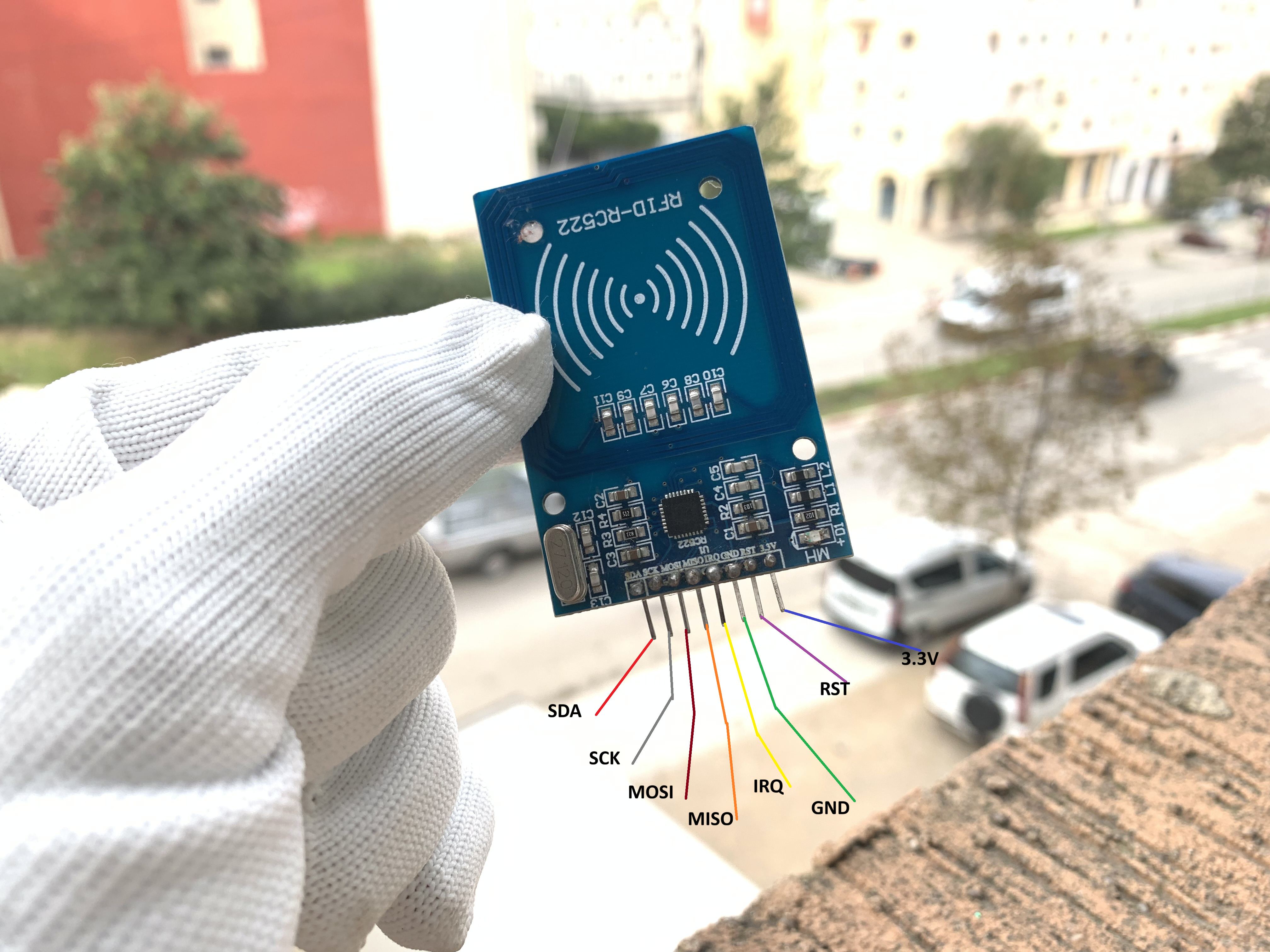
RC522 RFID module pinout
The module has 8 pins; you may not need to use all of them for simple projects. Here’s the pinout:
3.3V – Power Supply
RST – Reset
GND – Ground
IRQ – Interrupt (optional)
MISO – Master In Slave Out
MOSI – Master Out Slave In
SCK – Clock
SDA/SS – Slave Select for SPI
Only 3.3V, RST, GND, MISO, MOSI, SCK, and SDA are used for most Arduino projects.
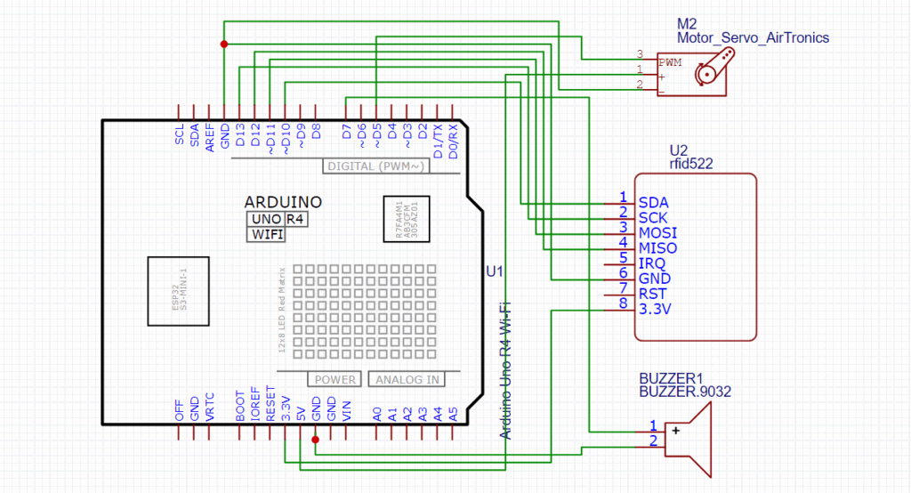
Circuit Diagram
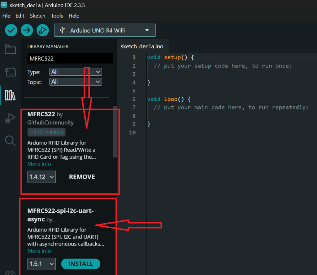
Install the MFRC522 library
Make sure to install the MFRC522 library to send and receive from RFID cards and key fobs electromagnetic waves at 13.56 million cycles per second.
Open the Arduino IDE and click on library manager.
In the search bar, type “MFRC522” and look for the library named “MFRC522 by GithubCommunity” or “MFRC522 by Miguel Balboa”.
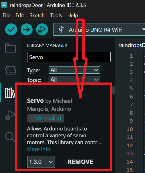
Install the Servo library
Make sure to install the Servo library to send and receive from RFID cards and key fobs electromagnetic waves at 13.56 million cycles per second.
In the search bar, type “Servo” and look for the library named “Servo by Michael Margolis, Arduino”.
Arduino Code
#include <SPI.h>
#include <MFRC522.h>
#include <Servo.h>
Servo myservo;
#define SS_PIN 10
#define RST_PIN 9
#define Alarm 7
#define SERVO_PIN 5
int ServoPosition = 30;
MFRC522 mfrc522(SS_PIN, RST_PIN);
void setup() {
myservo.attach(SERVO_PIN);
Serial.begin(9600);
SPI.begin();
mfrc522.PCD_Init();
myservo.write(ServoPosition);
pinMode(Alarm, OUTPUT);
}
void loop() {
// RFID section
if (!mfrc522.PICC_IsNewCardPresent() || !mfrc522.PICC_ReadCardSerial()) {
return; // No new card, exit RFID part
}
// Read UID
Serial.print("UID tag: ");
String content = "";
for (byte i = 0; i < mfrc522.uid.size; i++) {
Serial.print(mfrc522.uid.uidByte[i] < 0x10 ? " 0" : " ");
Serial.print(mfrc522.uid.uidByte[i], HEX);
content.concat(String(mfrc522.uid.uidByte[i] < 0x10 ? " 0" : " "));
content.concat(String(mfrc522.uid.uidByte[i], HEX));
}
Serial.println();
Serial.println();
content.toUpperCase();
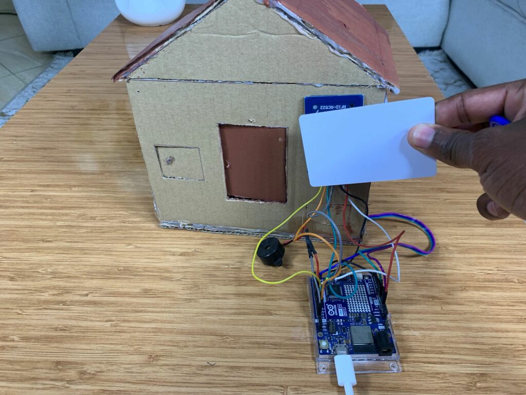
// Authorized card
if (content.substring(1) == "0B 23 9B 15") {
Serial.println("Access Granted - Door open");
ServoPosition = 75;
myservo.write(ServoPosition);
delay(2000);
ServoPosition = 30;
myservo.write(ServoPosition);
}
// Unauthorized card
else if (content.substring(1) == "52 EF E9 1C") {
Serial.println("Access Denied - Door closes");
digitalWrite(Alarm, HIGH);
delay(2500);
digitalWrite(Alarm, LOW);
ServoPosition = 30;
myservo.write(ServoPosition);
}
mfrc522.PICC_HaltA();
mfrc522.PCD_StopCrypto1();
}
How the Project Works
Includes the SPI library so the Arduino can speak to SPI devices (the RC522 RFID reader uses SPI).
#include <SPI.h>Includes the MFRC522 library which provides functions to control the RC522 RFID module (reading tags, getting UID, authentication helpers, etc).
#include <MFRC522.h>Includes the Servo library so the code can control a hobby servo motor.
#include <Servo.h>Creates a Servo object named myservo. You use this object to attach the servo to a pin and to set its position with .write().
Servo myservo;Defines a constant SS_PIN with value 10. This is the Arduino pin used as Slave Select (chip select) for the RFID module’s SPI connection.
#define SS_PIN 10Defines a constant named Alarm with value 7. This pin will be used as an output to control an alarm/buzzer/LED to indicate unauthorized access.
#define Alarm 7Defines a constant SERVO_PIN set to 5. The servo signal wire will be connected to digital pin 5.
#define SERVO_PIN 5Creates an integer variable ServoPosition and initializes it to 30. This represents the servo angle (degrees). The code uses 30° as the “closed” or default position.
int ServoPosition = 30;Creates an instance of the MFRC522 class called mfrc522 and tells it which pins to use for SS (chip select) and RST. This object is used to interact with the RFID reader.
MFRC522 mfrc522(SS_PIN, RST_PIN);Start of the setup() function — runs once when the Arduino boots or resets.
void setup() {Attaches the servo object to SERVO_PIN (pin 5). After this the library can control the servo connected to that pin.
myservo.attach(SERVO_PIN);Starts the Serial port at 9600 baud so the board can print messages to the Serial Monitor (useful for debugging and logging UID values).
Serial.begin(9600);Initializes the SPI bus. Must be called before using the RFID reader which communicates over SPI.
SPI.begin();Initialises the MFRC522 RFID reader (PCD = Proximity Coupling Device). This wakes the reader and prepares it to scan for cards.
mfrc522.PCD_Init();Writes the initial value of ServoPosition (30°) to the servo — sets the servo to the default/closed position at startup
myservo.write(ServoPosition);Sets the Alarm pin (pin 7) as an OUTPUT so the sketch can turn the alarm on and off.
pinMode(Alarm, OUTPUT);End of setup().
}Start of the loop() function — runs repeatedly.
void loop() {A comment indicating the RFID-related code follows.
// RFID sectionif (!mfrc522.PICC_IsNewCardPresent() || !mfrc522.PICC_ReadCardSerial()) {
This line checks whether a new RFID tag/card is present AND whether the library can read its serial (UID). PICC_IsNewCardPresent() returns true if a card just entered the field; PICC_ReadCardSerial() attempts to read the UID from the card. The ! and || mean: if no new card is present OR reading fails, do the next block.
return; // No new card, exit RFID part
If there is no new card or reading failed, return exits the current loop() invocation immediately — nothing else runs until the next loop iteration. This keeps the sketch from trying to process when there’s no tag.
Comment: next block prints and builds the UID string.
// Read UID
Prints the literal “UID tag: ” to the Serial Monitor as a prefix for the UID that will be printed next.
Serial.print("UID tag: ");
Creates an empty Arduino String named content. The code will append each UID byte to this string in hex format.
String content = "";
Starts a for loop that iterates over each byte of the UID. mfrc522.uid.size tells how many bytes the UID has (usually 4 for many tags).
for (byte i = 0; i < mfrc522.uid.size; i++) {
This prints either ” 0″ (leading zero) or a single space before the hex byte. It’s a way to ensure single-digit hex bytes get a leading zero in the display. mfrc522.uid.uidByte[i] < 0x10 checks if the byte is < 16 (i.e., would be a single hex digit).
Serial.print(mfrc522.uid.uidByte[i] < 0x10 ? " 0" : " ");
Prints the actual UID byte in hexadecimal to the Serial Monitor. The HEX parameter tells Serial.print to output hex.
Serial.print(mfrc522.uid.uidByte[i], HEX);
Appends the same leading-space or ” 0″ string to the content String. This mirrors what’s printed so content will contain the readable hex bytes separated by spaces, with leading zeros where needed.
content.concat(String(mfrc522.uid.uidByte[i] < 0x10 ? " 0" : " "));
Appends the hex representation of the UID byte to content.
content.concat(String(mfrc522.uid.uidByte[i], HEX));
End of for loop — by now content holds the UID as a string like ” 0B 23 9B 15″ (note the leading space before the first byte).
}
Prints a newline to the Serial Monitor.
Serial.println();
Prints another newline — creates a blank line for readability in the Serial Monitor.
Serial.println();
Converts the content String to uppercase so comparisons later are case-insensitive (ensures hex letters are A-F, not a-f).
content.toUpperCase();
Comment: the next if checks if the read UID matches an authorized UID.
- Authorized card
Compares the UID string to the authorized UID “0B 23 9B 15”. content.substring(1) removes the first character of content — which is the leading space added during concatenation. The code therefore compares the cleaned-up UID string. If it matches, the card is authorized.
if (content.substring(1) == "0B 23 9B 15") {
Writes a message to Serial Monitor indicating the card is authorized.
Serial.println("Access Granted - Door open");
Sets ServoPosition to 75 — likely the “open” position for the servo.
ServoPosition = 75;
Moves the servo to 75°, opening the door/lock.
myservo.write(ServoPosition);
Keeps the servo in the open position for 2000 ms (2 seconds). This is the time the door stays open.
delay(2000);
After the delay, resets ServoPosition back to 30° (closed).
ServoPosition = 30;
Moves the servo back to the closed position.
myservo.write(ServoPosition);
}
2. Unauthorised card
Comment: next block handles a specific “denied” UID.
else if (content.substring(1) == "52 EF E9 1C") { Checks if the UID matches "52 EF E9 1C". If yes, treat it as an unauthorized card (or as a specific denial case).
Prints a denial message to Serial Monitor.
Serial.println("Access Denied - Door closes");
Sets the alarm pin HIGH — turns on a buzzer or LED to alert that access is denied.
digitalWrite(Alarm, HIGH);
Keeps the alarm on for 2.5 seconds.
delay(2500);
Turns the alarm off.
digitalWrite(Alarm, LOW);
Ensures the servo is set to the closed position (30°) after denial.
ServoPosition = 30;
Writes the closed position to the servo (redundant if it was already there, but safe).
myservo.write(ServoPosition);
}
Tells the PICC (the tag) to halt. It’s a polite way to stop communication with the tag and prevents repeated reads of the same tag while it’s still in the field.
mfrc522.PICC_HaltA();
Stops any active encrypted session on the MFRC522 hardware. This is cleanup after reading/authenticating with a card.
mfrc522.PCD_StopCrypto1();
}
End of loop().
How the Project Works
When the system is powered on, the servo motor starts at 30°, which is the closed-door position. The RFID reader and alarm are also ready.
The RFID reader constantly scans for any card placed near it. If no card is detected, the system does nothing and waits.
If the card is not authorized:
The buzzer turns ON for a few seconds, and the door stays at 30°, remaining closed.
The system checks the UID:
- If the card is authorized:
The servo moves from 30° to 75°, opening the door. After a short pause, the servo returns to 30°, closing the door automatically.
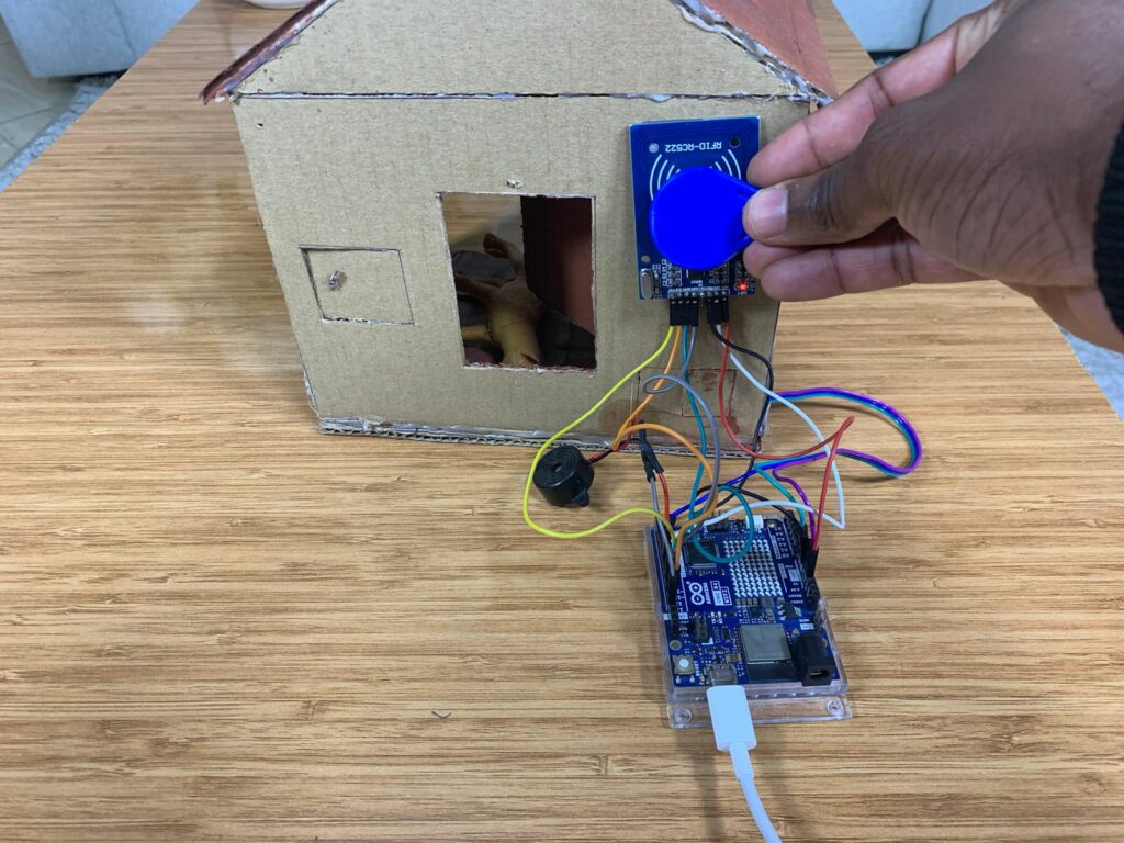
- If the card is not authorized:
The buzzer turns ON for a few seconds, and the door stays at 30°, remaining closed.
Good work
Hi, roeddwn i eisiau gwybod eich pris.
Helo George, beth yw pris y prosiect?