Interface Arduino Uno R4 WIFI with RFID RC522 Module
In today’s tutorial, I’ll show you how to interface the Arduino Uno R4 WiFi with the RC522 RFID module.
You’ll learn how to:
- Read RFID tags using the RC522 module
- Retrieve the UID code of each tag
- Use the UID in your own RFID-based projects
This guide is perfect for beginners who want to start building RFID applications with Arduino.
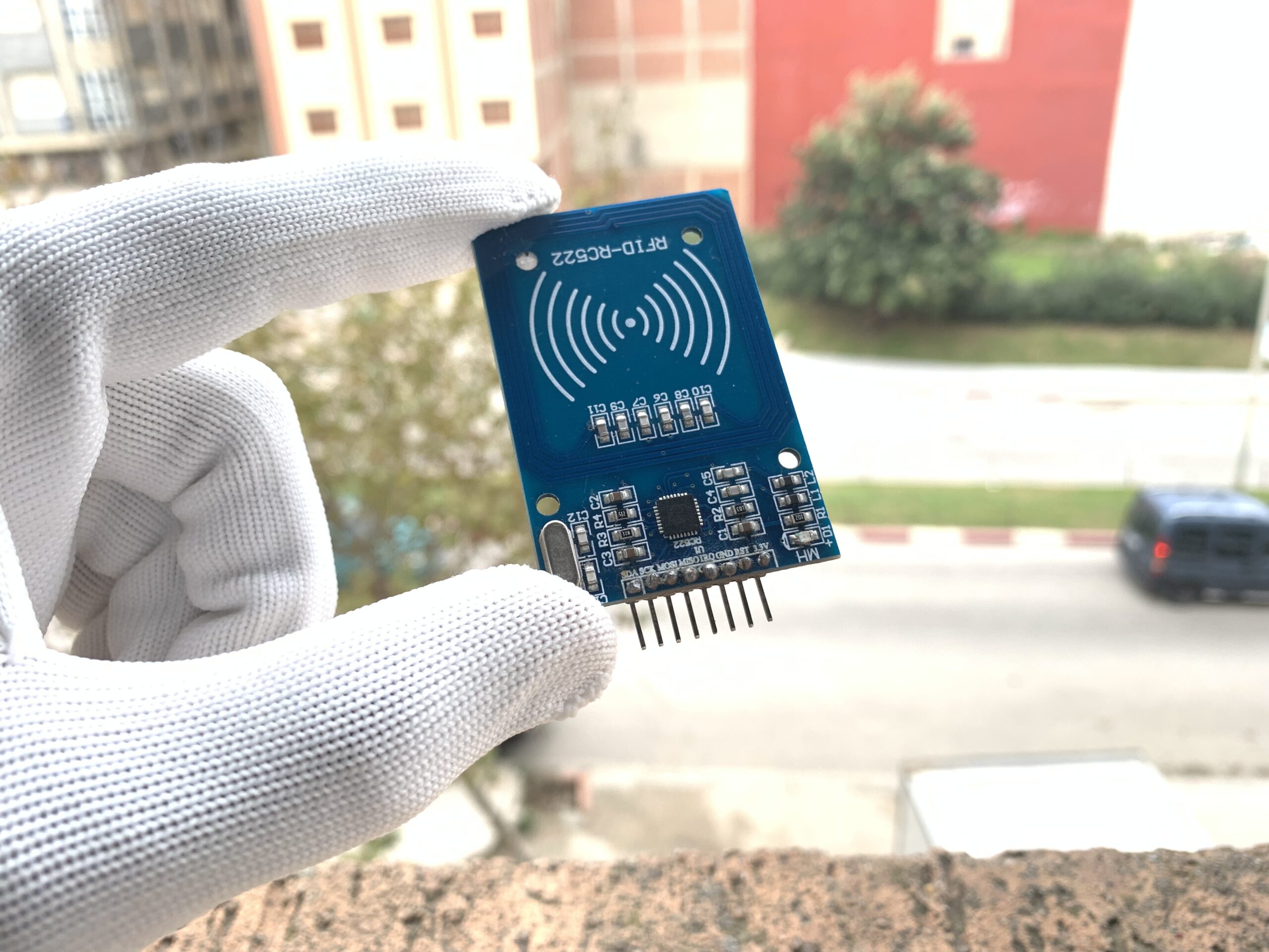
RFID RC522 Module
The RFID RC522 is a popular module based on the MFRC522 controller. It operates at a frequency of 13.56 MHz, which is the radio frequency used to communicate with RFID cards and tags. This means the module sends and receives electromagnetic waves at 13.56 million cycles per second.
How the RC522 Works
- The 13.56 MHz electromagnetic field can power passive cards (RFID cards and key fobs) without batteries.
- The module cannot read UHF cards (860–960 MHz) or low-frequency cards (125 kHz).
Supported Communication Protocols
The RC522 module can communicate with microcontrollers using multiple protocols:
- UART
- SPI (most commonly used)
- I2C
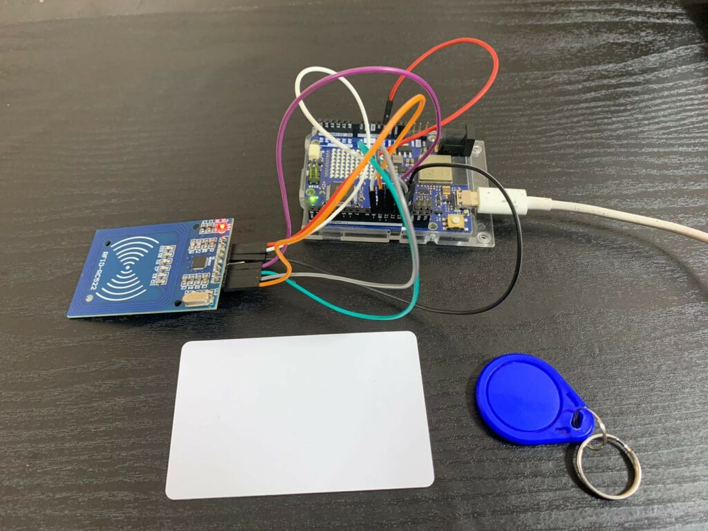
When purchased, the RC522 module usually comes with a white RFID card and a blue key fob.
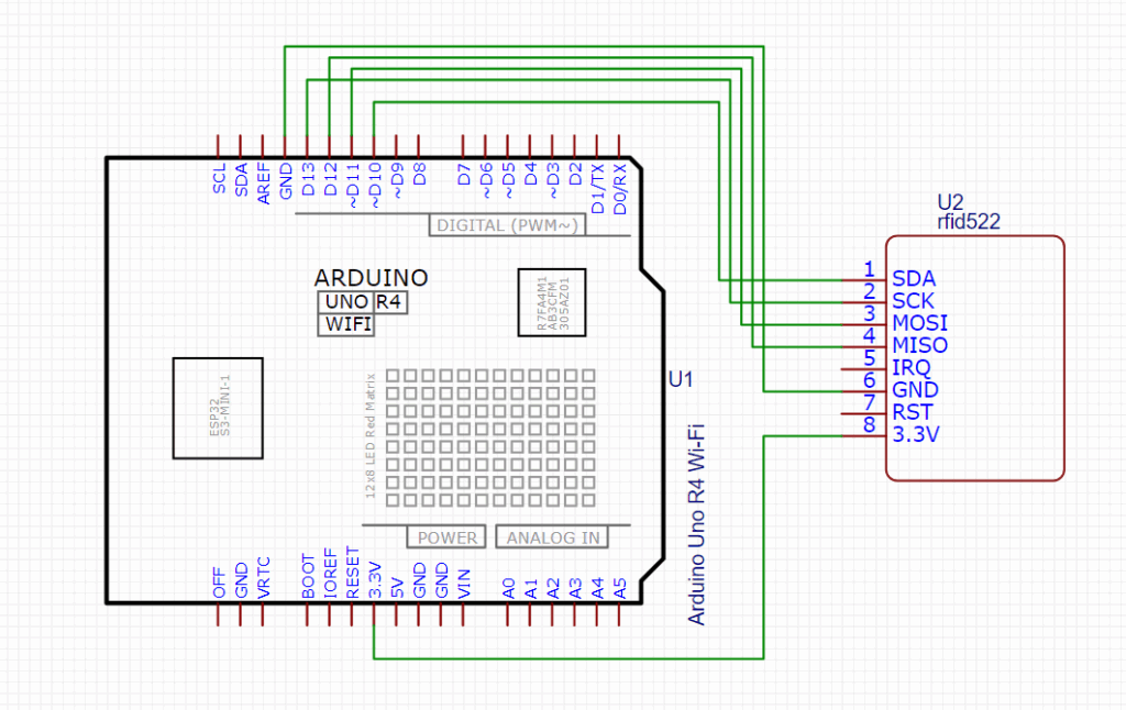
RC522 Pin Configuration
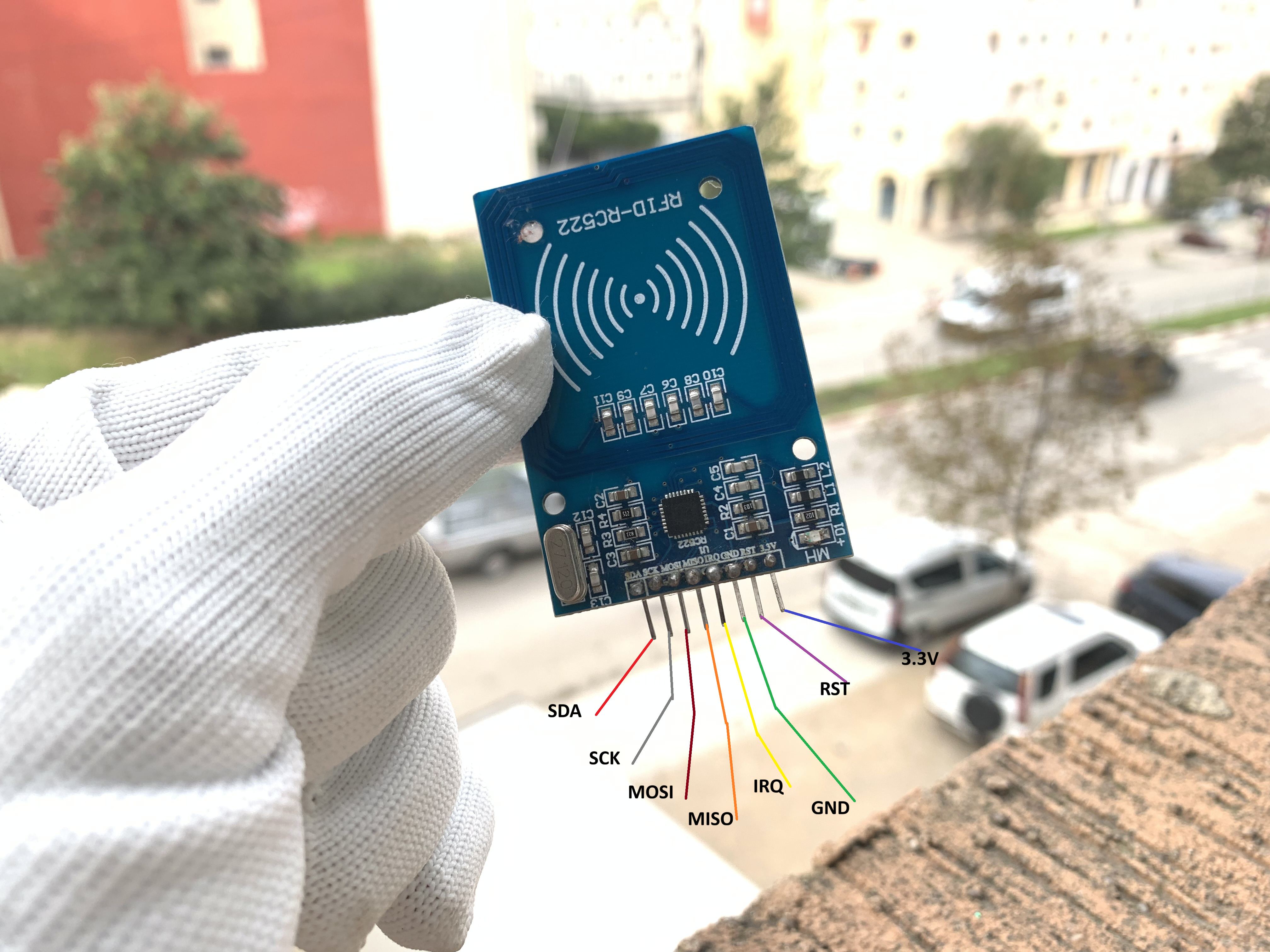
The module has 8 pins, but for simple projects, you may not need to use all of them. Here’s the typical pinout:
- SDA / SS – Slave select for SPI
- SCK – Clock
- MOSI – Master Out Slave In
- MISO – Master In Slave Out
- IRQ – Interrupt (optional)
- GND – Ground
- RST – Reset
- 3.3V – Power supply
For most Arduino projects, only SDA, SCK, MOSI, MISO, RST, GND, and 3.3V are required.
Components used
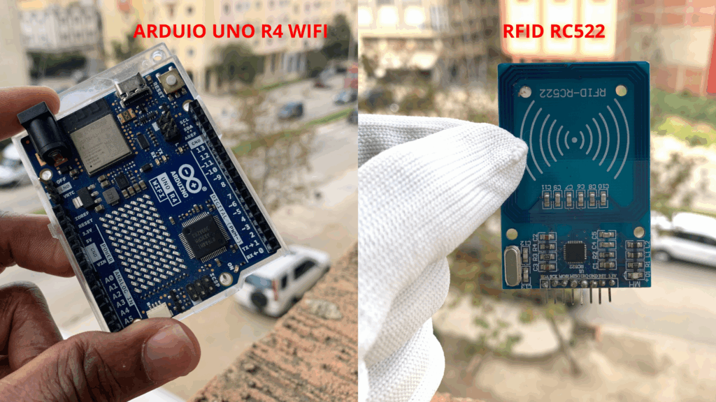
Interface with Arduino – Circuit Diagram
Arduino Code
Before using the MFRC522 RFID module, you need to install its library. We recommend using the MFRC522 library by GithubCommunity.
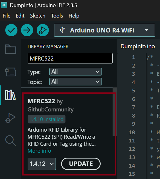
Step 1 — Install the Library
- Open the Arduino IDE.
- Go to Sketch → Include Library → Manage Libraries.
- In the Library Manager, search for MFRC522.
Install the version by GithubCommunity.
Step 2 — Open the Example Sketch
Once the library is installed:
- Go to File → Examples → MFRC522.
- Select the DumpInfo example.
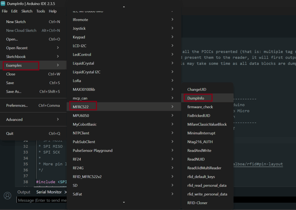
This sketch allows your Arduino to read RFID tags and display detailed information such as the UID and data blocks in the Serial Monitor.
#include <SPI.h>
#include <MFRC522.h>

#define RST_PIN         9          // Configurable, see typical pin layout above
#define SS_PIN          10         // Configurable, see typical pin layout above

MFRC522 mfrc522(SS_PIN, RST_PIN);  // Create MFRC522 instance

void setup() {
	Serial.begin(9600);		// Initialize serial communications with the PC
	while (!Serial);		// Do nothing if no serial port is opened (added for Arduinos based on ATMEGA32U4)
	SPI.begin();			// Init SPI bus
	mfrc522.PCD_Init();		// Init MFRC522
	delay(4);				// Optional delay. Some board do need more time after init to be ready, see Readme
	mfrc522.PCD_DumpVersionToSerial();	// Show details of PCD - MFRC522 Card Reader details
	Serial.println(F("Scan PICC to see UID, SAK, type, and data blocks..."));
}

void loop() {
	// Reset the loop if no new card present on the sensor/reader. This saves the entire process when idle.
	if ( ! mfrc522.PICC_IsNewCardPresent()) {
		return;
	}

	// Select one of the cards
	if ( ! mfrc522.PICC_ReadCardSerial()) {
		return;
	}

	// Dump debug info about the card; PICC_HaltA() is automatically called
	mfrc522.PICC_DumpToSerial(&(mfrc522.uid));
}
Read Tags with the MFRC522 Module
After wiring the Arduino and the MFRC522 RFID module together (see the connection diagram above), you’re ready to upload the sketch and start reading RFID cards.
Note: You must connect the MISO, MOSI, and SCK pins from the MFRC522 RFID module even if they are not written in the Arduino code, because they belong to the hardware communication protocol called SPI.
The Arduino Uno R4 WiFi board already knows how to use these pins internally. They are connected to a dedicated SPI hardware module inside the microcontroller that manages all SPI communication automatically.
You do not control these pins manually — the SPI hardware inside the Arduino handles them for you.
Step 1 — Upload the Sketch to Your Arduino
- Open the Arduino IDE.
- Load the RFID sketch provided in this tutorial.
- Click Verify to compile the code.
Click Upload to send it to your Arduino board.
Once the upload is complete, your Arduino is ready to communicate with the MFRC522 module.
Step 2 — Open the Serial Monitor
To see the card information in real time:
- Go to Tools → Serial Monitor,
- or press Ctrl + Shift + M on your keyboard.
Make sure the baud rate matches the value in your code (usually 9600 or 115200 depending on your sketch).
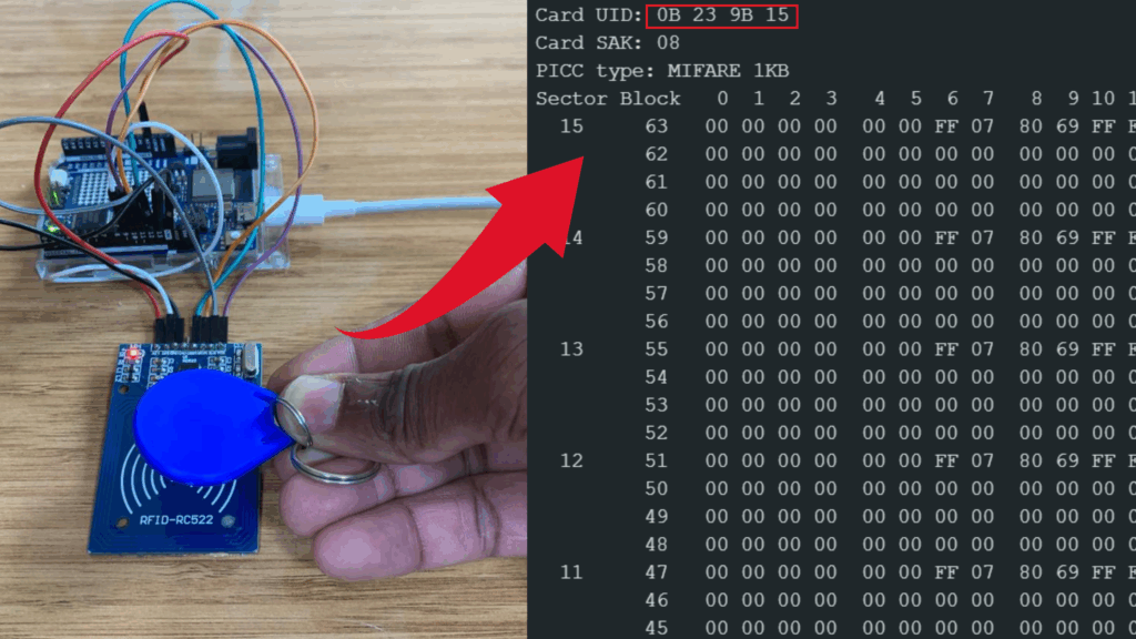
Step 3 — Scan Your RFID Card or Tag
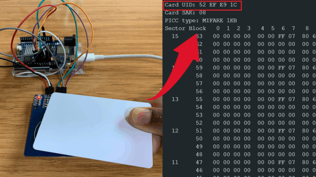
Place an RFID card or tag (also called PICC – Proximity Integrated Circuit Card) near the MFRC522 antenna.
You will see the following information appear in the Serial Monitor:
- UID (Unique Identifier) of the card
- Card type (MIFARE Classic, MIFARE Ultralight, etc.)
- Readable data blocks depending on the tag type and permissions
This allows you to identify each tag and confirm that the module is working correctly.
Reading Key fob UID
Reading RFID Tag
Love it
Thank you!/Merci beaucoup!