
DIY Mini Radar Kit: 1.8″ SPI TFT Display & Ultrasonic Scanning with Arduino Uno R3
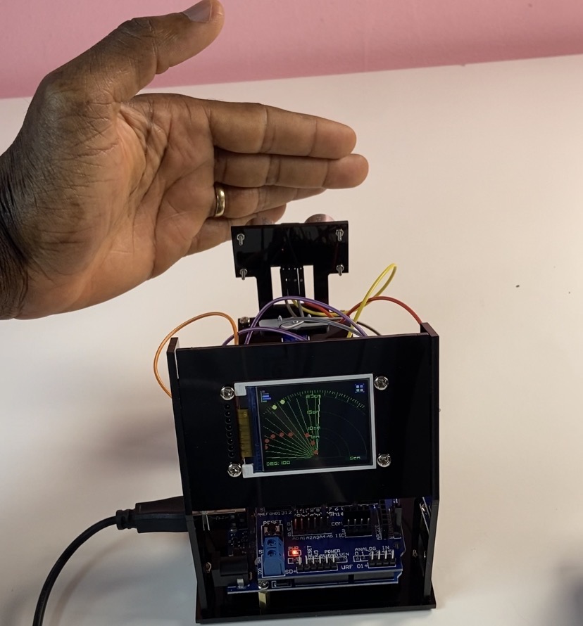
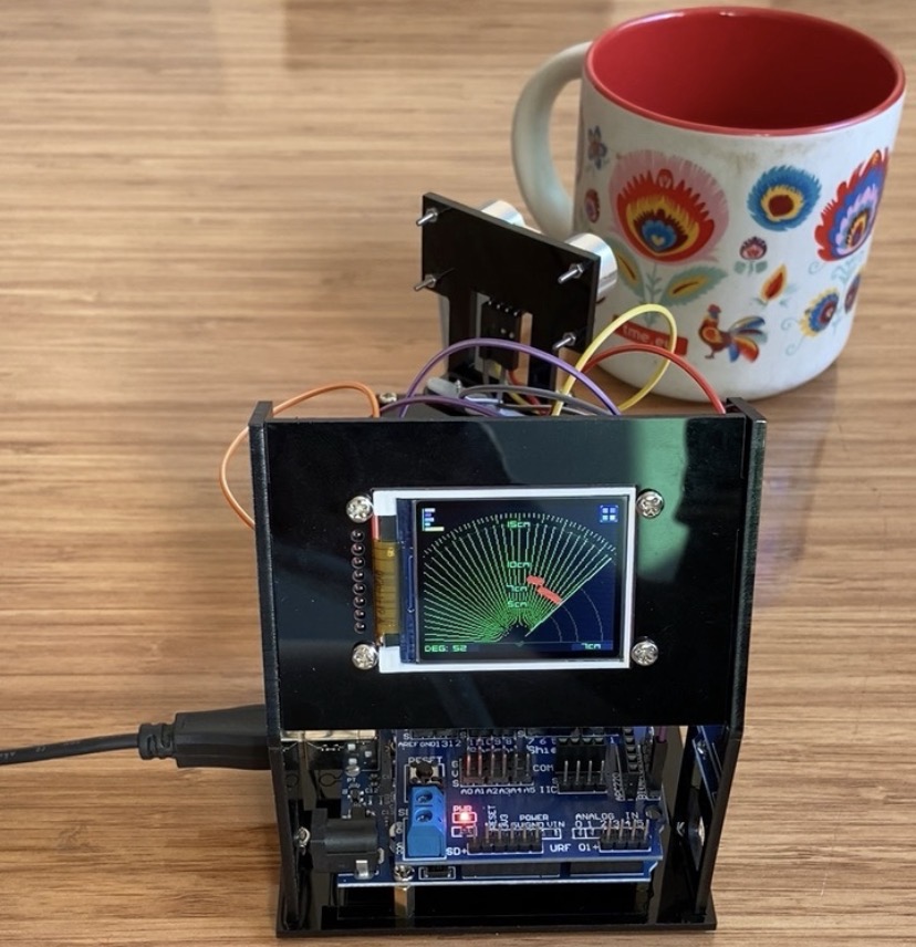
Construct a standalone desktop radar scanner that shows nearby obstacles in real time on a colorful 1.8-inch TFT screen! This project uses an Arduino Uno R3 and a Sensor Shield v5.0 to track things up to 100 cm away by putting an HC-SR04 ultrasonic sensor onto a revolving SG90 servo motor.
Watch the full video
For written instructions, continue reading this page, or watch the video guide.
Components Used
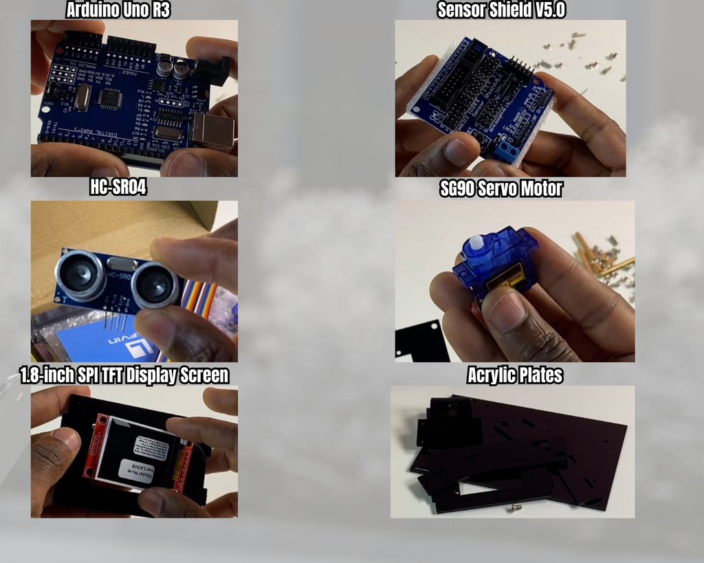
- Microcontroller: Arduino Uno R3 Development Board
- Expansion Shield: Sensor Shield Version 5.0
- Sensor: HC-SR04 Ultrasonic Distance Sensor
- Actuator: SG90 Micro Servo Motor
- Display: 1.8-inch SPI TFT Display Screen (128×160 resolution, ST7735)
- Frame & Hardware:
Find the assembly kit in TEMU
Ultrasonic Module Distance Measurement Scanning Detector Kit
Frame & Hardware
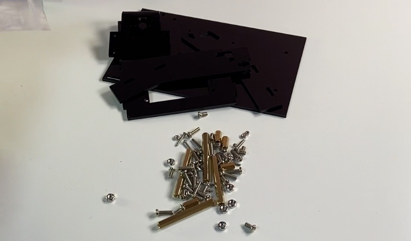
- Laser-cut Acrylic Base, Side, Display, and Sensor Mounting Plates
- 4x M3 x 40mm Copper Standoffs
- 8x M3 x 10mm Copper Standoffs
- 6x M3 x 10mm Screws & 6x M3 Nuts
- 1x M2 x 12mm Screw & 1x M2 Nut
- 1x M1.6 x 12mm Screw & 1x M1.6 Nut
- Servo mounting screws and horn package
Mechanical Assembly Steps
Prepare & Assemble Ultrasonic Sensor Horn
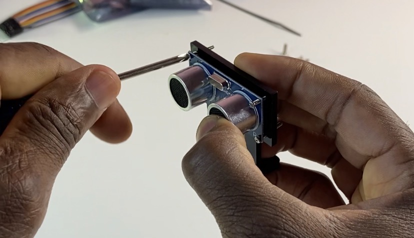
Every acrylic plate should have its protective coating removed. Using the M1.6 nut and M1.6 x 12mm screw, attach the HC-SR04 ultrasonic sensor to the appropriate acrylic plate.
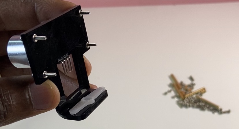
Next, use the screws included in the servo motor package to fasten the servo horn to the rear of this sensor plate assembly.
Mount Servo Motor & Base Standoffs
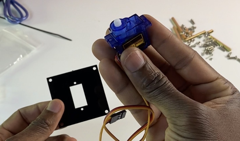
Use the M2 x 12mm screw and M2 nut to fasten the SG90 servo motor to its acrylic plate.
Thread four M3 x 40mm copper standoffs into the acrylic base plate
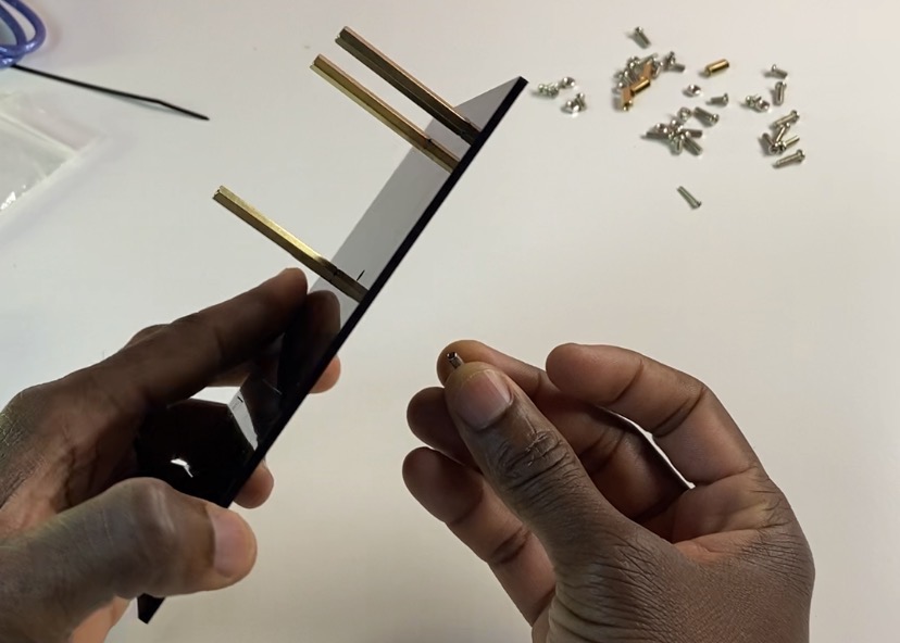
Mount the acrylic plate containing the servo motor onto four M3 x 40mm copper standoffs that have been threaded into the acrylic base plate.
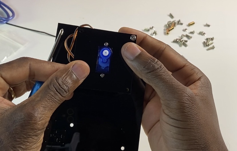
Using its central mounting screw, fasten the servo horn—which has the sensor assembly attached—to the servo motor shaft.
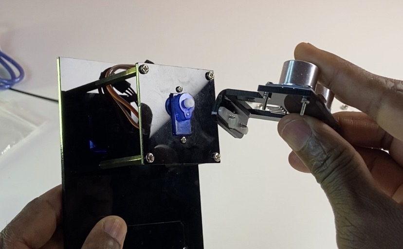
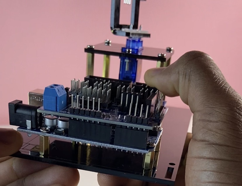
Mount Arduino Uno R3 & Sensor Shield
Four M3 x 10mm copper standoffs should be fastened to the base plate.
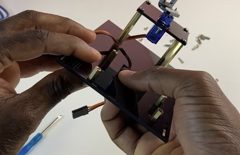
Place the Arduino Uno R3 board on top of these standoffs and fasten it with four more M3 x 10mm standoffs.
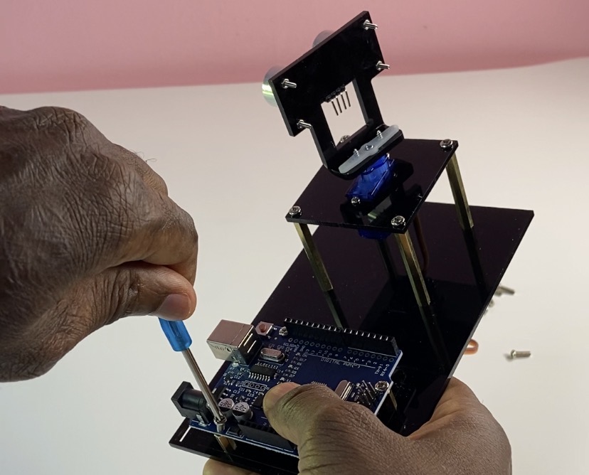
Firmly align all of the pins on the Arduino Uno R3 by pressing the Sensor Shield Version 5.0 onto it.
Enclose Acrylic Frame & TFT Screen
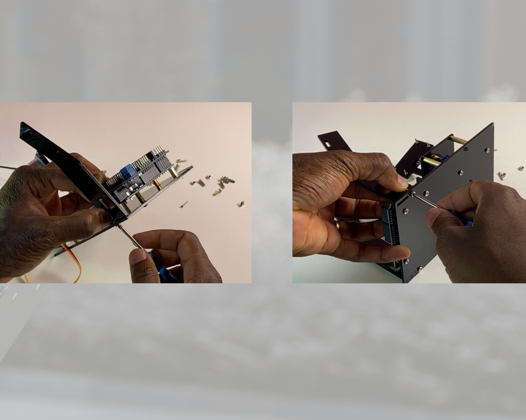
Next to the microcontroller, fasten the left and right acrylic plates with two M3 nuts and two M3 x 10mm screws.
Secure the 1.8-inch SPI TFT display to its mounting plate using four M3 x 10mm screws and four M3 nuts.
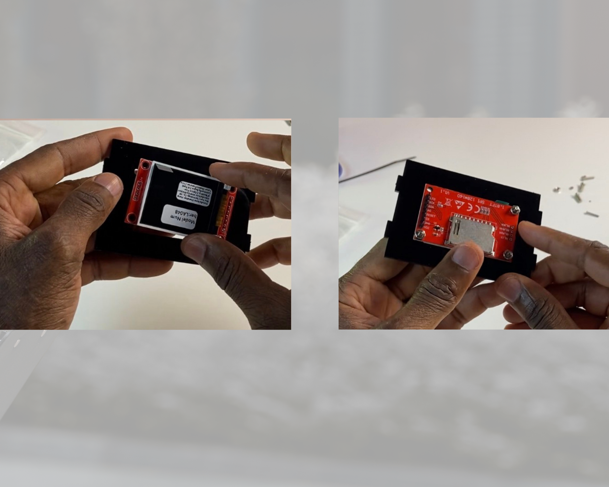
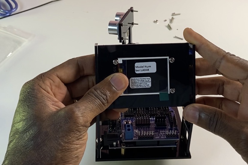
Place this assembled screen unit between the two side plates after fastening the 1.8-inch SPI TFT display to its mounting plate with four M3 x 10mm screws and four M3 nuts.
Circuit Wiring & Schematic Description
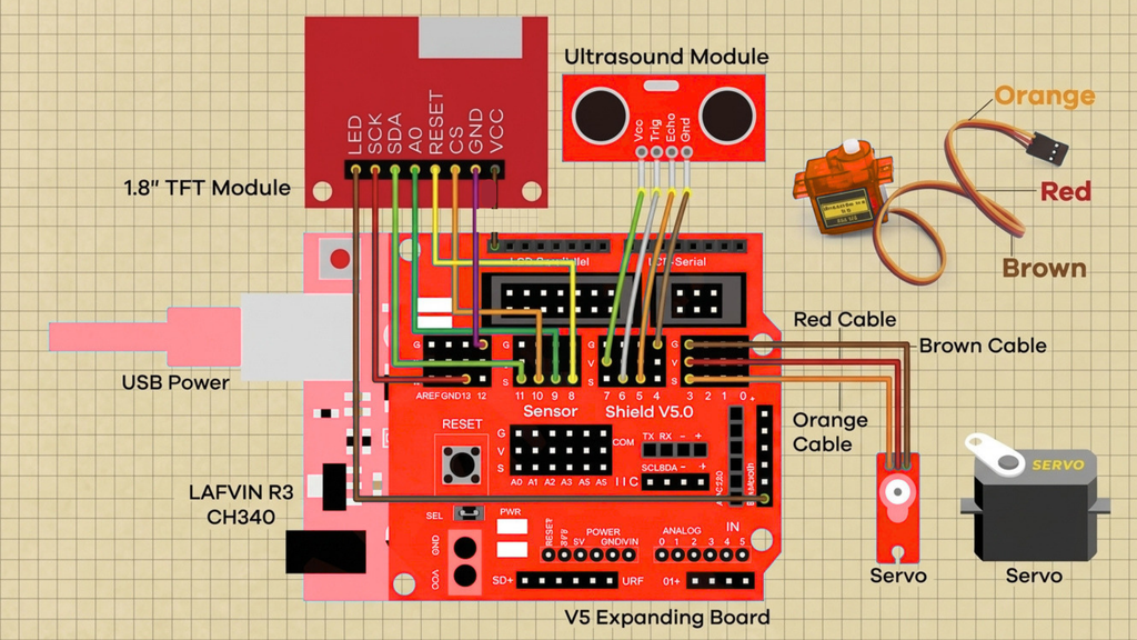
Using the Sensor Shield v5.0, connect the peripherals to the dedicated headers:
| Sensor Shield Version 5.0 | SG90 Servo Motor | 1.8″ SPI TFT Display | HC-SR04 Ultrasonic Sensor |
| Pin 3 | Signal Pin | ||
| VCC | Pin (+5V) | ||
| Ground | GND | GND | GND |
| Pin 10 | CS (Chip Select) | ||
| Pin 8 | RESET | ||
| Pin 9 | A0 (Data/Command) | ||
| Pin 11 | SDA (MOSI) | ||
| Pin 13 | SCK (Clock) | ||
| LED (Backlight) | Connect to one of the Bluetooth line header VCC/3.3V pin | ||
| Pin 5 | Echo | ||
| Pin 6 | Trig | ||
| V Pin (+5V) | VCC | ||
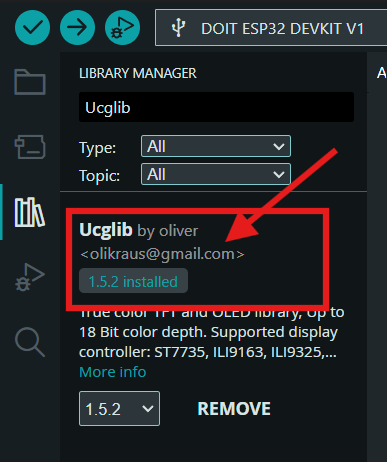
Ucglib library
High-performance graphics driver for color TFT displays (ST7735 hardware SPI support)
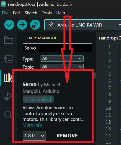
Servo library
Built-in hardware timer control for the SG90 servo motor
SPI library
Built-in communication library for driving the TFT display
Arduino Code
/* mini radar kit */
#include <Servo.h>
#include <SPI.h>
#include "Ucglib.h"

#define trigPin   6          // Ultrasonic Module Trig -> D6
#define echoPin   5          // Ultrasonic Module Echo -> D5
#define ServoPin  3          // Servo Signal -> D3

int Ymax = 128;              // Vertical pixels of the screen
int Xmax = 160;              // Horizontal pixels of the screen
int Xcent = Xmax / 2;         // Horizontal screen center position
int base = 118;              // Baseline position
int scanline = 105;          // Radar scan line length

Servo baseServo;
Ucglib_ST7735_18x128x160_HWSPI ucg(/*cd=*/ 9, /*cs=*/ 10, /*reset=*/ 8);

void setup(void)
{
  ucg.begin(UCG_FONT_MODE_SOLID); // Initialize screen
  ucg.setRotate90();               // Set to horizontal orientation

  pinMode(trigPin, OUTPUT);        // Set Trig Pin mode
  pinMode(echoPin, INPUT);         // Set Echo Pin mode
  Serial.begin(115200);            // Serial communication speed
  baseServo.attach(ServoPin);      // Initialize servo

  // Screen startup interface
  ucg.setFontMode(UCG_FONT_MODE_TRANSPARENT);
  ucg.setColor(0, 0, 100, 0);
  ucg.setColor(1, 0, 100, 0);
  ucg.setColor(2, 20, 20, 20);
  ucg.setColor(3, 20, 20, 20);
  ucg.drawGradientBox(0, 0, 160, 128);
  ucg.setPrintDir(0);
  ucg.setColor(0, 5, 0);
  ucg.setPrintPos(27, 42);
  ucg.setFont(ucg_font_logisoso18_tf);
  ucg.print("Mini Radar");
  ucg.setColor(0, 255, 0);
  ucg.setPrintPos(25, 40);
  ucg.print("Mini Radar");
  ucg.setFont(ucg_font_helvB08_tf);
  ucg.setColor(0, 255, 0);
  ucg.setPrintPos(40, 100);
  ucg.print("Testing...");
  baseServo.write(90);

  // Test servo movement across 180 degrees
  for(int x = 0; x < 180; x += 5) {
    baseServo.write(x);
    delay(50);
  }
  ucg.print("OK!");
  delay(500);

  cls(); // Clear screen
  ucg.setFont(ucg_font_orgv01_hr);
  ucg.setFontMode(UCG_FONT_MODE_SOLID);
}

void cls() {
  ucg.setColor(0, 0, 0, 0);
  for(int s = 0; s < 128; s += 8) {
    for(int t = 0; t < 160; t += 16) {
      ucg.drawBox(t, s, 16, 8);
    }
  }
}

int calculateDistance() {
  long duration;
  digitalWrite(trigPin, LOW);
  delayMicroseconds(2);
  digitalWrite(trigPin, HIGH);
  delayMicroseconds(10);
  digitalWrite(trigPin, LOW);

  duration = pulseIn(echoPin, HIGH);
  return duration * 0.034 / 2;
}

void fix_font() {
  ucg.setColor(0, 180, 0);
  ucg.setPrintPos(70, 128 - 120 + 7);
  ucg.print("100cm");
  ucg.setPrintPos(70, 128 - 85 - 11);
  ucg.print("75cm");
  ucg.setPrintPos(70, 128 - 60 - 8);
  ucg.print("50cm");
  ucg.setPrintPos(70, 128 - 35 - 4);
  ucg.print("25cm");
}

void fix() {
  ucg.setColor(0, 40, 0);
  ucg.drawDisc(Xcent, base + 1, 3, UCG_DRAW_ALL);
  ucg.drawCircle(Xcent, base + 1, 115, UCG_DRAW_UPPER_LEFT);
  ucg.drawCircle(Xcent, base + 1, 115, UCG_DRAW_UPPER_RIGHT);
  ucg.drawCircle(Xcent, base + 1, 86, UCG_DRAW_UPPER_LEFT);
  ucg.drawCircle(Xcent, base + 1, 86, UCG_DRAW_UPPER_RIGHT);
  ucg.drawCircle(Xcent, base + 1, 58, UCG_DRAW_UPPER_LEFT);
  ucg.drawCircle(Xcent, base + 1, 58, UCG_DRAW_UPPER_RIGHT);
  ucg.drawCircle(Xcent, base + 1, 29, UCG_DRAW_UPPER_LEFT);
  ucg.drawCircle(Xcent, base + 1, 29, UCG_DRAW_UPPER_RIGHT);
  ucg.drawLine(0, base + 1, Xmax, base + 1);

  ucg.setColor(0, 120, 0);
  for(int i = 40; i < 140; i += 2) {
    if (i % 10 == 0)
      ucg.drawLine(105 * cos(radians(i)) + Xcent, base - 105 * sin(radians(i)), 113 * cos(radians(i)) + Xcent, base - 113 * sin(radians(i)));
    else
      ucg.drawLine(110 * cos(radians(i)) + Xcent, base - 110 * sin(radians(i)), 113 * cos(radians(i)) + Xcent, base - 113 * sin(radians(i)));
  }

  ucg.setColor(0, 200, 0);
  ucg.drawLine(0, 0, 0, 18);
  for(int i = 0; i < 5; i++) {
    ucg.setColor(random(255), random(255), random(255));
    ucg.drawBox(2, i * 4, random(14) + 2, 3);
  }

  ucg.setColor(0, 0, 180);
  ucg.drawFrame(146, 0, 14, 14);
  ucg.setColor(0, 0, 60);
  ucg.drawHLine(148, 0, 10);
  ucg.drawVLine(146, 2, 10);
  ucg.drawHLine(148, 13, 10);
  ucg.drawVLine(159, 2, 10);

  ucg.setColor(random(255), random(255), random(255));
  ucg.drawBox(148, 2, 4, 4);
  ucg.setColor(0, 220, 0);
  ucg.drawBox(148, 8, 4, 4);
  ucg.setColor(random(255), random(255), random(255));
  ucg.drawBox(154, 8, 4, 4);
  ucg.setColor(random(255), random(255), random(255));
  ucg.drawBox(154, 2, 4, 4);

  ucg.setColor(0, 0, 90);
  ucg.drawTetragon(62, 123, 58, 127, 98, 127, 102, 123);
  ucg.setColor(0, 0, 160);
  ucg.drawTetragon(67, 123, 63, 127, 93, 127, 97, 123);
  ucg.setColor(0, 255, 0);
  ucg.drawTetragon(72, 123, 68, 127, 88, 127, 92, 123);
}

void loop(void) {
  int distance;

  fix();
  fix_font();

  // Sweep backward (180 -> 4 degrees)
  for (int x = 180; x > 4; x -= 2) {
    baseServo.write(x);

    int f = x - 4;
    ucg.setColor(0, 255, 0);
    ucg.drawLine(Xcent, base, scanline * cos(radians(f)) + Xcent, base - scanline * sin(radians(f)));
    f += 2;
    ucg.setColor(0, 128, 0);
    ucg.drawLine(Xcent, base, scanline * cos(radians(f)) + Xcent, base - scanline * sin(radians(f)));
    f += 2;
    ucg.setColor(0, 0, 0);
    ucg.drawLine(Xcent, base, scanline * cos(radians(f)) + Xcent, base - scanline * sin(radians(f)));

    distance = calculateDistance();

    if (distance < 100) {
      ucg.setColor(255, 0, 0);
      ucg.drawDisc(1.15 * distance * cos(radians(x)) + Xcent, -(1.15 * distance * sin(radians(x))) + base, 1, UCG_DRAW_ALL);
    } else {
      ucg.setColor(255, 255, 0);
      ucg.drawDisc(116 * cos(radians(x)) + Xcent, -116 * sin(radians(x)) + base, 1, UCG_DRAW_ALL);
    }

    Serial.print("Degree:  ");
    Serial.print(x);
    Serial.print("    ,Distance:   ");
    Serial.println(distance);

    if (x > 70 && x < 110) fix_font();

    ucg.setColor(0, 0, 155, 0);
    ucg.setPrintPos(0, 126);
    ucg.print("DEG: ");
    ucg.setPrintPos(24, 126);
    ucg.print(x);
    ucg.print("  ");
    ucg.setPrintPos(125, 126);
    ucg.print("  ");
    ucg.print(distance);
    ucg.print("cm  ");
  }

  delay(50);
  cls();
  fix();
  fix_font();

  // Sweep forward (1 -> 176 degrees)
  for (int x = 1; x < 176; x += 2) {
    baseServo.write(x);

    int f = x + 4;
    ucg.setColor(0, 255, 0);
    ucg.drawLine(Xcent, base, scanline * cos(radians(f)) + Xcent, base - scanline * sin(radians(f)));
    f -= 2;
    ucg.setColor(0, 128, 0);
    ucg.drawLine(Xcent, base, scanline * cos(radians(f)) + Xcent, base - scanline * sin(radians(f)));
    f -= 2;
    ucg.setColor(0, 0, 0);
    ucg.drawLine(Xcent, base, scanline * cos(radians(f)) + Xcent, base - scanline * sin(radians(f)));

    distance = calculateDistance();

    if (distance < 100) {
      ucg.setColor(255, 0, 0);
      ucg.drawDisc(1.15 * distance * cos(radians(x)) + Xcent, -(1.15 * distance * sin(radians(x))) + base, 1, UCG_DRAW_ALL);
    } else {
      ucg.setColor(255, 255, 0);
      ucg.drawDisc(116 * cos(radians(x)) + Xcent, -116 * sin(radians(x)) + base, 1, UCG_DRAW_ALL);
    }

    Serial.print("Degree:  ");
    Serial.print(x);
    Serial.print("    ,Distance:   ");
    Serial.println(distance);

    if (x > 70 && x < 110) fix_font();

    ucg.setColor(0, 0, 155, 0);
    ucg.setPrintPos(0, 126);
    ucg.print("DEG: ");
    ucg.setPrintPos(24, 126);
    ucg.print(x);
    ucg.print("   ");
    ucg.setPrintPos(125, 126);
    ucg.print("   ");
    ucg.print(distance);
    ucg.print("cm   ");
  }

  delay(50);
  cls();
}
How It Works
The SG90 servo motor is continuously swept back and forth across a 180-degree field of vision by the Arduino Uno R3. At each angle step, the HC-SR04 ultrasonic sensor releases high-frequency sound pulses and counts the reflection time to calculate the exact distance of neighboring obstructions.
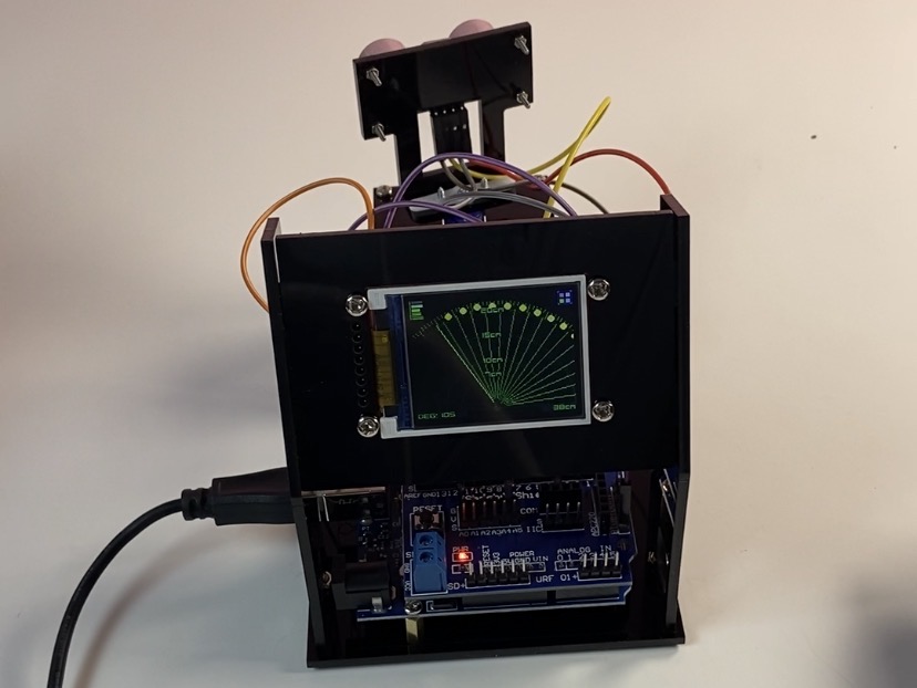
The Ucglib graphics driver processes these real-time angle and distance values to plot sweeping green scan lines onto the TFT display. Any object detected within a 100cm range appears as a distinct red dot on the radar grid, while the screen dynamically updates the current angle degree and distance reading along the bottom edge.