

Ultrasonic Sensor Scanning Radar with TFT Display | Distance Measurement Kit Demo.
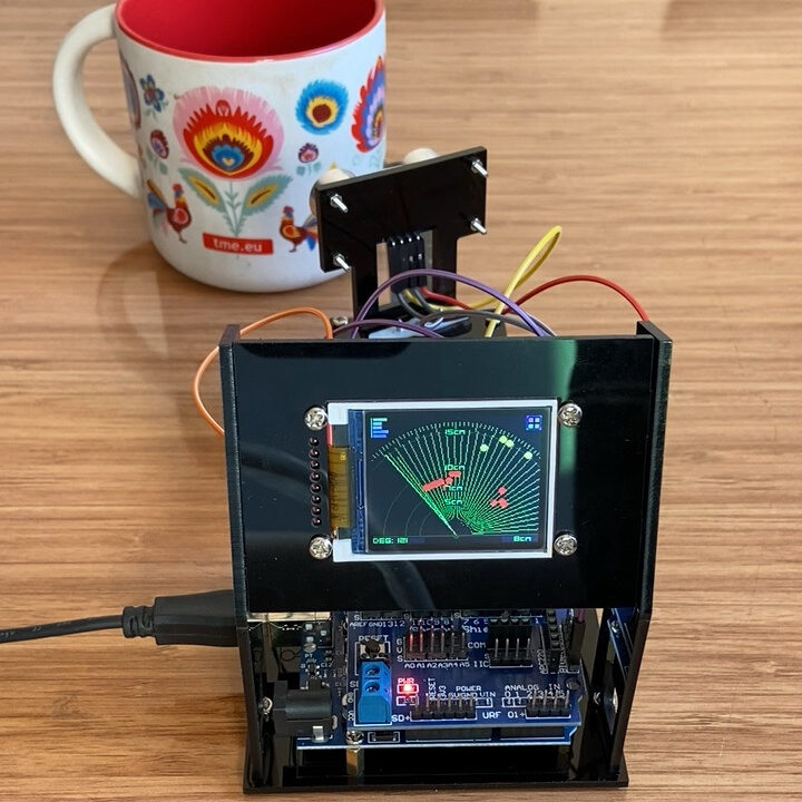
An Ultrasonic Sensor Scanning Radar with TFT Display is a classic DIY microcontroller project that mimics a real radar system using acoustic sound waves instead of radio waves.
It mounts an ultrasonic sensor onto a servo motor to sweep across an arc, plotting nearby obstacle distances in real time onto a color TFT display.
Watch the full video
For written instructions, continue reading this page, or watch the video guide.
What Makes It Useful
- All-in-One Learning: Combines motor movement, distance measurement, and screen rendering into one complete workflow.
- Standalone Display: Visualizes scan data instantly on the dedicated TFT panel without requiring a connected PC or external monitor.
- Arduino Compatible: Open-source architecture makes it easy to modify the sweep angle, adjust detection thresholds, or add custom audio alerts.
Availability: The Ultrasonic Sensor Scanning Radar with TFT Display | Distance Measurement Kit Demo is available for purchase on TEMU.
Parts Required
Do you want the item in this post ?
Download TEMU app : Download TEMU app on your phone
After downloading the TEMU app click on this link: ESP32 CAM Robot Car Kit
Question 1: What should I do if my sensor or display isn’t responding?
Answer:
First, check all physical jumper wire connections against the pinout diagram. Ensure your micro-controller is outputting the correct voltage (3.3V vs 5V required by the module). Next, run a simple I2C or Serial scanner sketch in the Arduino IDE to verify that the board detects the sensor’s address on the communication bus.
Question 2: Why am I getting garbage characters or a blank screen on my display?
Answer:
Garbage characters usually indicate a baud rate mismatch. Ensure the baud rate set in your code’s Serial.begin() function matches the speed selected in your Serial Monitor or display driver. Blank screens often result from missing display initialization libraries, incorrect CS/DC pin assignments, or insufficient power delivery from the USB port.
Question 3: Can I power this project using a battery instead of a USB cable?
Answer:
Yes. You can power the board using a 3.7V LiPo battery (if your development board has a built-in battery management circuit) or an external 5V step-up boost converter connected to the 5V / VIN pin. Always check that the peak current draw of your active sensors or displays does not exceed the battery regulator’s limit.
Question 4: Where can I download the required libraries for this code?
Answer:
All required libraries can be installed directly through the Arduino IDE Library Manager (Sketch > Include Library > Manage Libraries). Simply search for the library names listed in the prerequisites section of this tutorial and click Install.