
Interfacing RC522 RFID Module with ESP32: UID Scanner & Access Control System
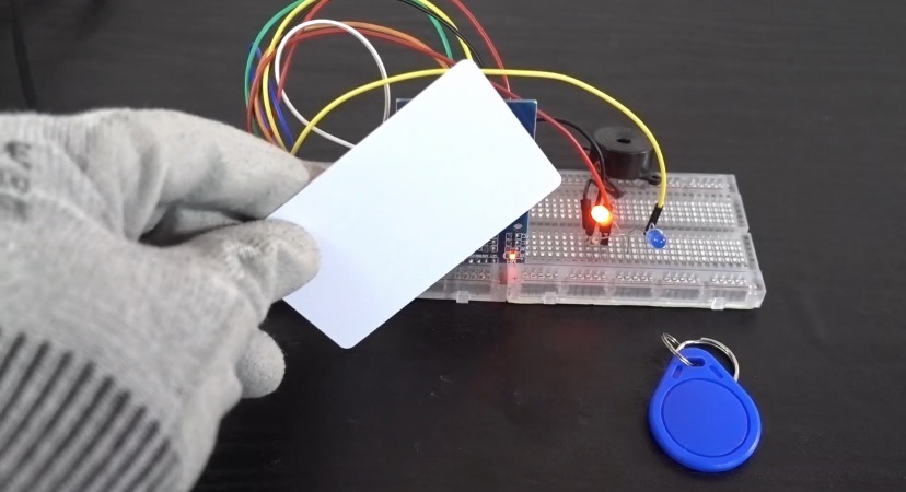
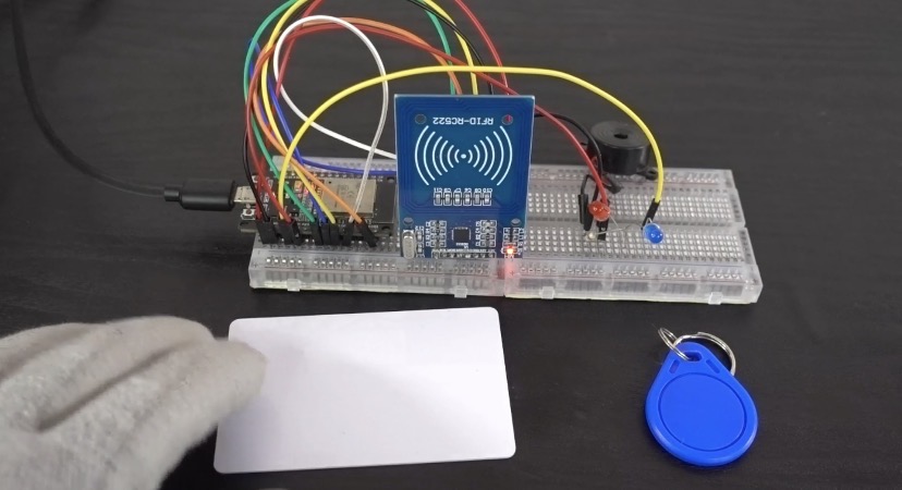
Radio-Frequency Identification (RFID) technology is a cornerstone of modern security, access control, and inventory tracking. In this project, we interface an RC522 RFID module with an ESP32 microcontroller using high-speed SPI communication. The project is split into two actionable steps: first, we scan unknown RFID tags to retrieve their unique identification (UID) numbers via the Serial Monitor; second, we program an access control logic where an authorized key fob (blue tag) unlocks a Blue LED, while any unauthorized RFID card (white card) triggers a Red LED and a warning buzzer tied to the same GPIO line. Whether you are building a smart door lock, attendance tracker, or personal security gate, this guide covers the underlying RFID physics, complete circuit schematics, library dependencies, and both Arduino C++ sketches required to bring it to life.
What is the RC522 RFID Reader Module?
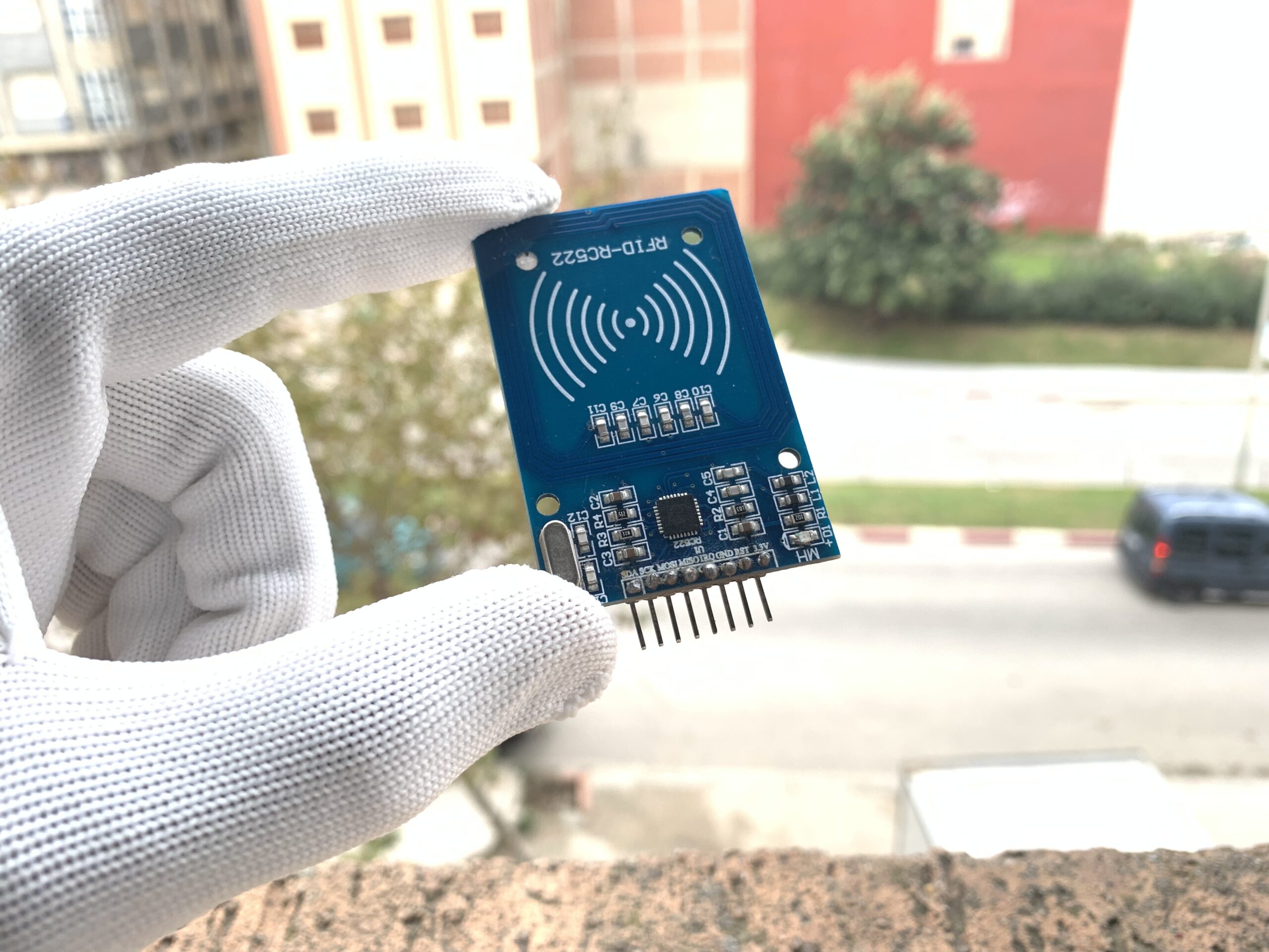
The RFID RC522 is a popular module based on the MFRC522 integrated circuit from NXP Semiconductors. It operates at a high frequency of 13.56 MHz, sending and receiving electromagnetic waves at 13.56 million cycles per second to communicate with compatible tags.
How the RC522 Works
- Passive Tag Powering: The 13.56 MHz electromagnetic field generated by the RC522’s antenna powers passive transponders (such as standard RFID cards and key fobs) through inductive coupling, allowing tags to transmit data back without needing onboard batteries.
- Frequency Limits: The module specifically reads 13.56 MHz High Frequency (HF) tags (e.g., ISO/IEC 14443A / MIFARE). It cannot read Ultra-High Frequency (UHF) cards (860–960 MHz) or Low-Frequency (LF) cards (125 kHz).
- Communication Protocols: The RC522 chip supports UART, SPI, and I2C interfaces. SPI is the default and most commonly used protocol due to its high transfer speed and reliability.
- Included Accessories: Standard RC522 kits usually ship with one white ISO credit-card-sized RFID card and one blue key fob tag.
RC522 Pin Configuration
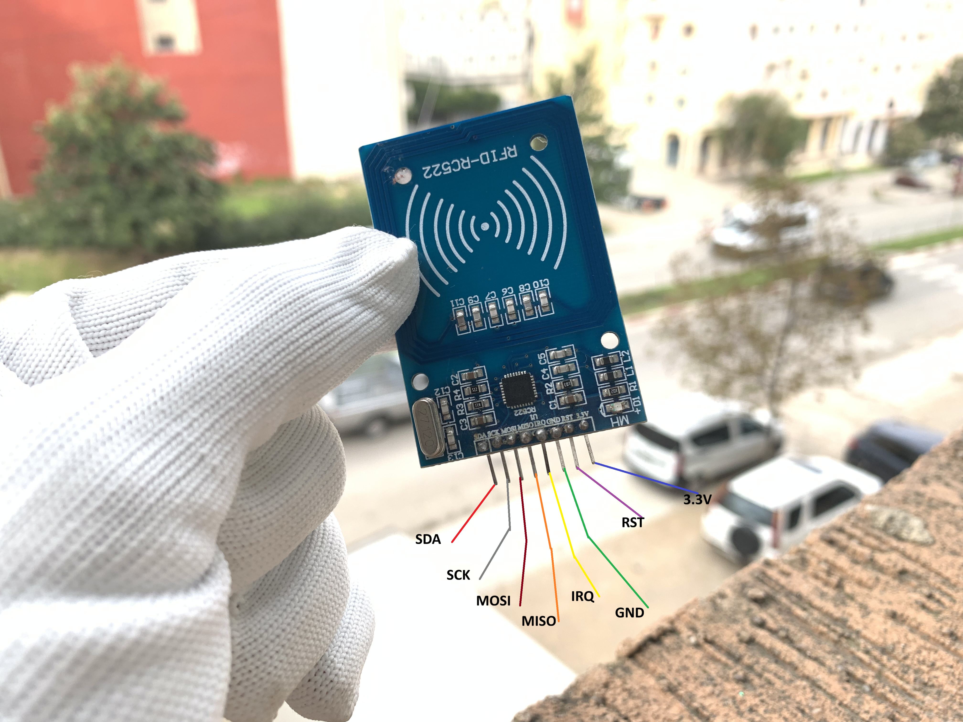
- SDA / SS: Slave Select (SPI Chip Select)
- SCK: Serial Clock
- MOSI: Master Out Slave In
- MISO: Master In Slave Out
- IRQ: Interrupt Request Line (optional)
- GND: Ground Reference
- RST: Hardware Reset Line
- 3.3V: Main Power Supply
Components Used
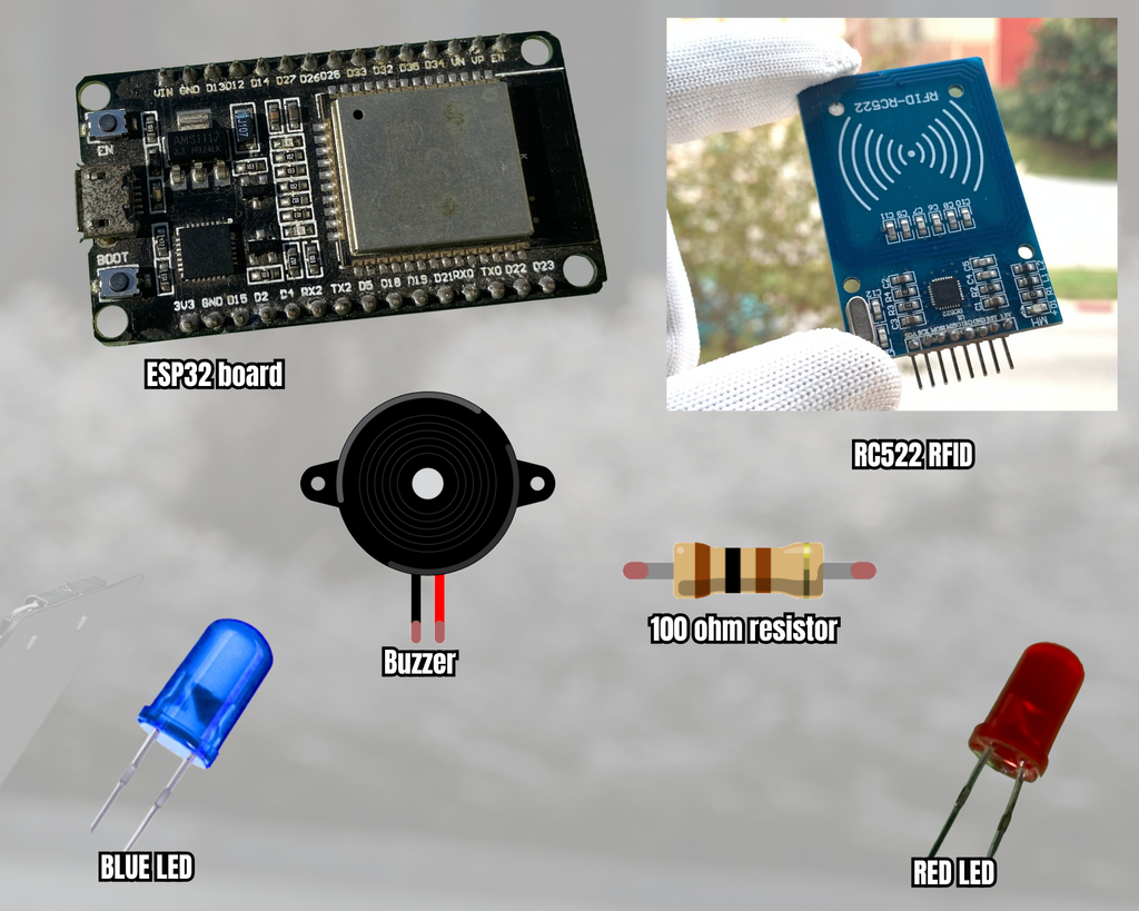
- ESP32 Development Board
- RC522 13.56 MHz RFID Reader Module
- Blue RFID Key Fob Tag (Authorized Tag)
- White RFID Smart Card (Unauthorized Tag)
- 5mm Blue LED
- 5mm Red LED
- 5V/3.3V Active Buzzer
- 100Ω Current-Limiting Resistor (shared cathode return path)
Required Libraries
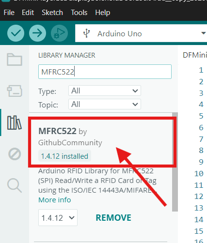
MFRC522 by GithubCommunity (Version 1.4.12) – Essential driver for handling MFRC522 register commands and PICC communication over SPI.
Step 1: Scanning RFID Tag UID Codes
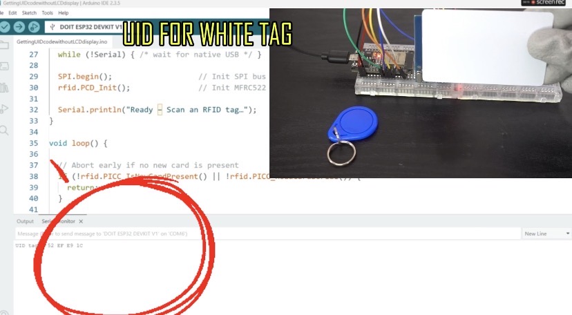
Upload this first code to the ESP32 to discover the unique hexadecimal UID numbers.
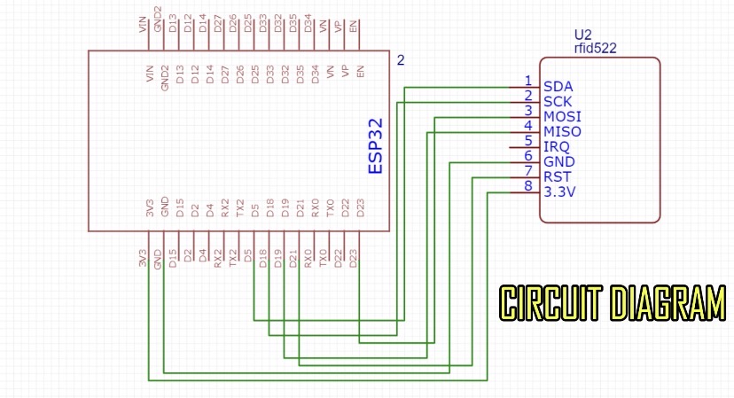
Circuit diagram for step 1
Arduino code for step 1
/*
  RFID UID Reader (Serial Only)
  -----------------------------
  Wiring (MFRC522 → ESP32 ):
    SDA  → GPIO5   (SS)         — change SS_PIN below if you wire SS elsewhere
    SCK  → GPIO18   (SCK)
    MOSI → GPIO23   (MOSI)
    MISO → GPIO19   (MISO)
    RST  → GPIO21    — change RST_PIN below if you wire RESET elsewhere
    3V3  → 3.3 V
    GND  → GND
*/

#include <SPI.h>          // Hardware‑SPI for MFRC522
#include <MFRC522.h>      // RFID driver

// -----------------------------------------------------------------------------
// Pin definitions – adjust to match your wiring
// -----------------------------------------------------------------------------
#define SS_PIN   5        // MFRC522 SS  (SDA)  — change if needed
#define RST_PIN  21       // MFRC522 RST — change if needed

MFRC522 rfid(SS_PIN, RST_PIN);   // RFID reader instance

void setup() {
  Serial.begin(115200);            // Open serial port
  while (!Serial) { /* wait for native USB */ }

  SPI.begin();                   // Init SPI bus
  rfid.PCD_Init();               // Init MFRC522 reader

  Serial.println("Ready – Scan an RFID tag…");
}

void loop() {

  // Abort early if no new card is present
  if (!rfid.PICC_IsNewCardPresent() || !rfid.PICC_ReadCardSerial()) {
    return;
  }

  // ---------------------------------------------------------------------------
  // A tag has been detected – print its UID:
  // ---------------------------------------------------------------------------
  Serial.print(F("UID tag : "));
  for (byte i = 0; i < rfid.uid.size; i++) {
    if (rfid.uid.uidByte[i] < 0x10) Serial.print('0');  // leading zero for one‑digit hex
    Serial.print(rfid.uid.uidByte[i], HEX);
    if (i < rfid.uid.size - 1) Serial.print(' ');       // space between bytes
  }
  Serial.println();
  Serial.println();

  rfid.PICC_HaltA();             // Stop reading this PICC
}
Discover the unique hexadecimal UID number of the key fob.
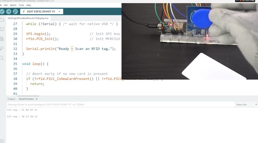
Discover the unique hexadecimal UID number of the RFID card.
Step 2: Implementation Code (Access Control System)
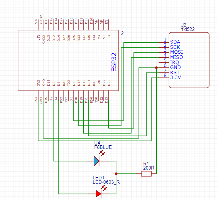
Copy the 4-byte UID retrieved in Step 1 for your authorized blue key fob and replace {0x0B, 0x23, 0x9B, 0x15} inside authorizedUID[].
Circuit diagram for step 2
Arduino code for step 2
#include <SPI.h>           // SPI library for RFID
#include <MFRC522.h>       // RFID library
#include <Wire.h>          // I2C library (optional)

// RFID pins
#define SS_PIN 5           // SDA for RFID
#define RST_PIN 21         // RST for RFID

#define Blue_LED 2         // Blue LED for authorized key fob access
#define Red_LED 4          // Red LED & Buzzer for unauthorized access

MFRC522 rfid(SS_PIN, RST_PIN);    // Create MFRC522 instance

// Predefined UID for authorized card (Replace with your blue key fob's actual UID)
byte authorizedUID[] = {0x0B, 0x23, 0x9B, 0x15};

void setup() {
  Serial.begin(115200);

  pinMode(Blue_LED, OUTPUT);
  pinMode(Red_LED, OUTPUT);

  digitalWrite(Blue_LED, LOW);
  digitalWrite(Red_LED, LOW);

  SPI.begin();             // Init SPI bus
  rfid.PCD_Init();         // Init RFID reader
  Serial.println("Place your RFID card near the reader...");
}

void loop() {
  // Wait for a new RFID card
  if (!rfid.PICC_IsNewCardPresent() || !rfid.PICC_ReadCardSerial()) {
    return;
  }

  Serial.print("UID tag: ");
  String content = "";
  for (byte i = 0; i < rfid.uid.size; i++) {
    Serial.print(rfid.uid.uidByte[i] < 0x10 ? " 0" : " ");
    Serial.print(rfid.uid.uidByte[i], HEX);
    content.concat(String(rfid.uid.uidByte[i] < 0x10 ? " 0" : " "));
    content.concat(String(rfid.uid.uidByte[i], HEX));
  }
  Serial.println();

  // Check if UID matches authorized key fob
  bool authorized = true;
  for (byte i = 0; i < rfid.uid.size; i++) {
    if (rfid.uid.uidByte[i] != authorizedUID[i]) {
      authorized = false;
      break;
    }
  }

  // Access control decision
  if (authorized) {
    Serial.println("Access Granted!");
    digitalWrite(Blue_LED, HIGH);
    delay(2000);
    digitalWrite(Blue_LED, LOW);
  } else {
    Serial.println("Access Denied!");
    digitalWrite(Red_LED, HIGH); // Powers both Red LED and Buzzer on GPIO 4
    delay(2000);
    digitalWrite(Red_LED, LOW);
  }

  rfid.PICC_HaltA();  // Stop reading current card
}
How it works
When the authorized blue key fob is tapped against the scanner, the MFRC522 reads its unique 4-byte UID and transfers the array across the SPI bus to the ESP32. The microcontroller compares these bytes against the hardcoded authorizedUID[] array, detects a complete match, and sets GPIO 2 HIGH for two seconds—illuminating the Blue LED to signal “Access Granted.”
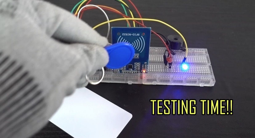
When an unauthorized card (such as the white RFID card) is presented, the ESP32 detects a byte mismatch during array evaluation and triggers the access denial sequence. Driving GPIO 4 HIGH for two seconds simultaneously activates the Red LED and triggers the parallel-connected active buzzer, delivering an instant visual and audible warning for “Access Denied.”