
Sound-Triggered Latch: Turn Sound into a Button with ESP32-S3
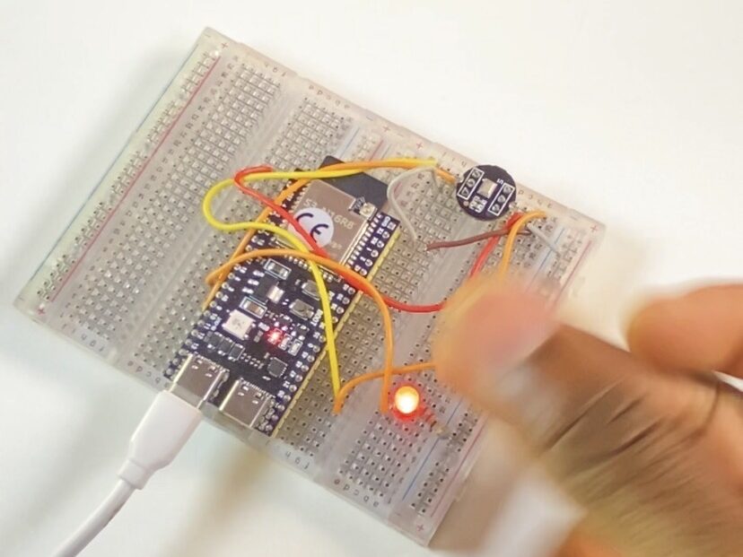
Have you ever wished you could simply clap or snap your fingers to control actual hardware? Conventional buttons are functional, but using sound as an interactive switch elevates your microcontrollers to a whole new level.
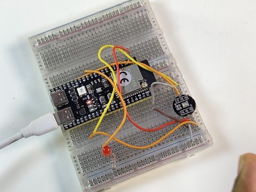
In this project, we are use the ESP32-S3 to transform the INMP441 digital microphone into a hands-free toggle switch. Our code will identify abrupt sound peaks rather than merely detecting sound levels in order to latch an LED ON and OFF—just like a physical button, but entirely touchless. Let’s go over the digital signal processing and hardware configuration required to ensure dependability.
Parts required
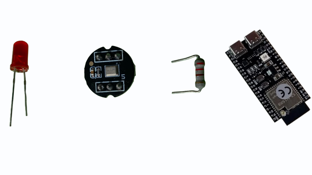
- LED
- INMP441 I2S Omnidirectional Digital Microphone Module
- 100Ω Resistor
- ESP32-S3
Where to Get the Parts (Available on TEMU)
Building this project won’t break the bank! All the hardware components used in this tutorial—including the ESP32 development board, the INMP441 I2S MEMS microphone module, breadboards, LEDs, and jumper wires—are readily available on TEMU. They offer super affordable multi-packs for parts like the INMP441 and ESP32 boards, making TEMU a convenient one-stop shop to grab all your project supplies before you start wiring.
Download the TEMU app first and create an account: https://temu.to/k/exyzc2cpy6m after downloading the TEMU app and creating an account, click on these links:
INMP441 microphone: https://temu.to/k/eg0id11wbwh; ESP32-S3: https://temu.to/k/e7h0zlijiog
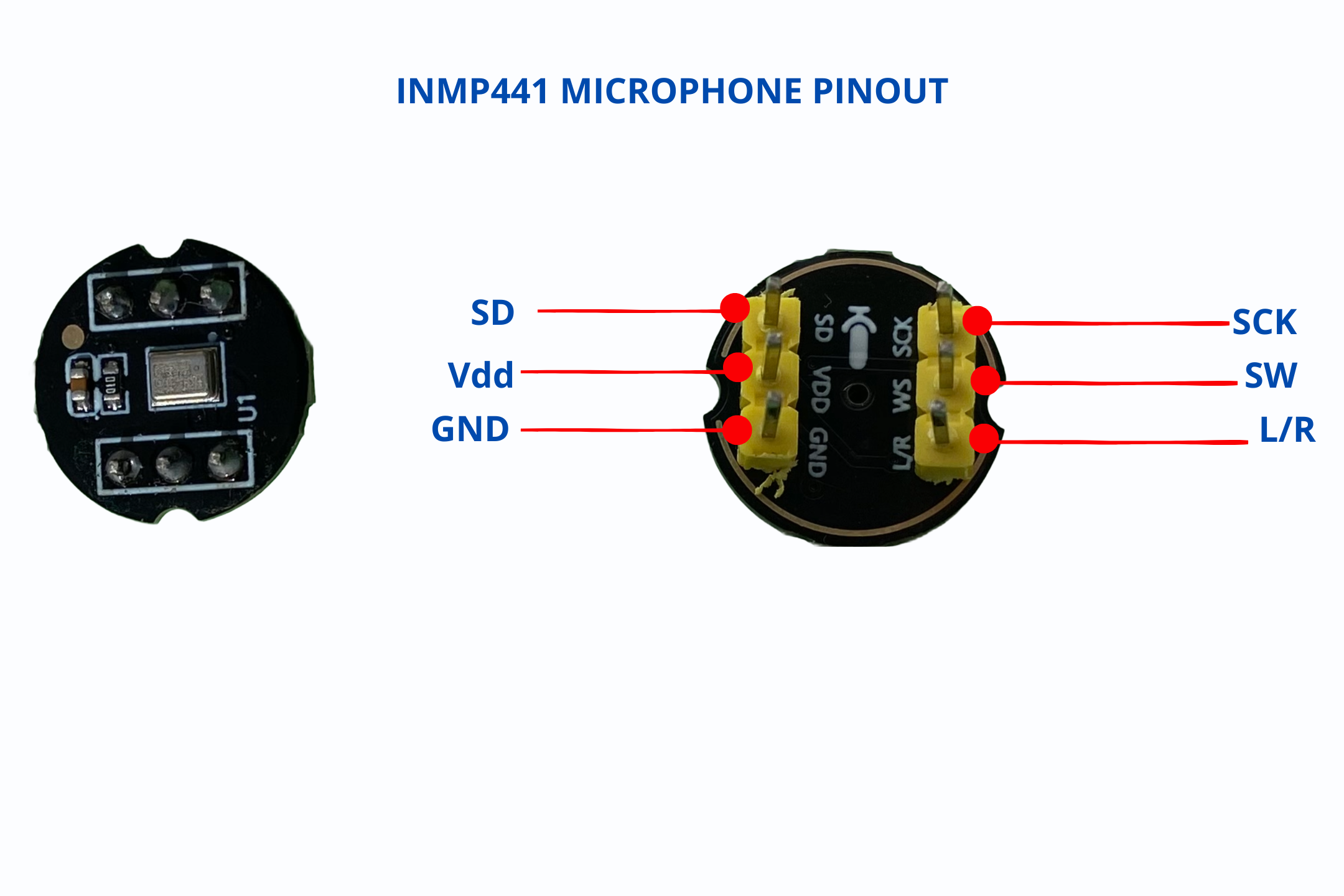
INMP441P microphone pinout
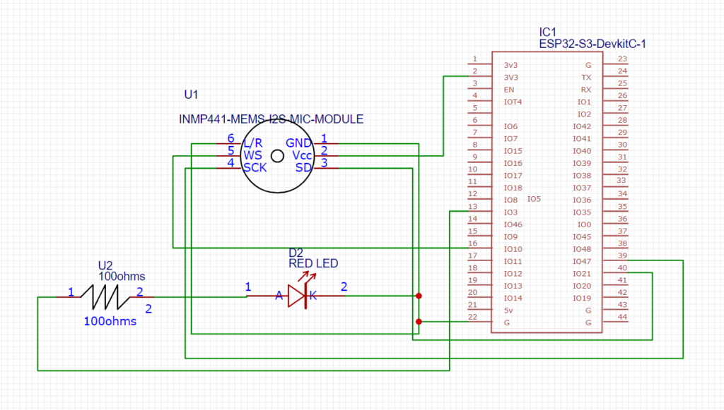
Circuit Diagram
Library used
You do not need to install anything separately.
If using Arduino IDE: The driver/i2s.h header is included automatically when you install the ESP32 Board Support Package via the Board Manager (esp32 by Espressif Systems).
Your IDE installs the full Espressif core framework in the background when you enable ESP32 board support. All of the native hardware drivers for the ESP32’s internal functions, such as I2S audio, I2C, SPI, PWM, and Bluetooth/Wi-Fi, are included with that framework.
Therefore, #include will build without the need to find or download any additional libraries as long as you have an ESP32 board chosen in your board menu.
Arduino code
#include <driver/i2s.h>
#include <Arduino.h>

#define SAMPLE_BUFFER_SIZE 512
#define SAMPLE_RATE 16000

// I2S Microphone Pins
#define I2S_BCLK_MIC 47  // gpio 47 to SCK
#define I2S_LRC_MIC 10   // GPIO 10 SW
#define I2S_DIN_MIC 21   // gpio 21 to SD

// LR pin to GNS
#define I2S_SD_SPK 4     // DAC shutdown pin.
#define I2S_MIC_PORT I2S_NUM_0

// Threshold and LED configuration
const int soundThreshold = 2500;  // Adjust based on your environment
const int ledPin = 3;             // Target LED pin

// Toggle & Debounce Variables
bool ledState = false;             // Stores the current ON/OFF state
unsigned long lastTriggerTime = 0; // Stores the timestamp of the last toggle
const unsigned long cooldownMs = 300; // Minimum time (in ms) between toggles

i2s_config_t i2s_config = {
    .mode = (i2s_mode_t)(I2S_MODE_MASTER | I2S_MODE_RX),
    .sample_rate = SAMPLE_RATE,
    .bits_per_sample = I2S_BITS_PER_SAMPLE_16BIT,
    .channel_format = I2S_CHANNEL_FMT_ONLY_LEFT,
    .communication_format = I2S_COMM_FORMAT_I2S_MSB,
    .intr_alloc_flags = ESP_INTR_FLAG_LEVEL1,
    .dma_buf_count = 4,
    .dma_buf_len = 1024,
    .use_apll = false,
    .tx_desc_auto_clear = false,
    .fixed_mclk = 0
};

i2s_pin_config_t i2s_mic_pins = {
    .bck_io_num = I2S_BCLK_MIC,
    .ws_io_num = I2S_LRC_MIC,
    .data_out_num = I2S_PIN_NO_CHANGE,
    .data_in_num = I2S_DIN_MIC
};

int16_t raw_samples[SAMPLE_BUFFER_SIZE];

void setup() {
  Serial.begin(115200);
  pinMode(ledPin, OUTPUT);
  digitalWrite(ledPin, LOW); // Initialize LED as OFF

  // Initialize I2S
  if (i2s_driver_install(I2S_MIC_PORT, &i2s_config, 0, NULL) != ESP_OK) {
    Serial.println("I2S driver installation failed!");
    while(1);
  }

  if (i2s_set_pin(I2S_MIC_PORT, &i2s_mic_pins) != ESP_OK) {
    Serial.println("I2S pin configuration failed!");
    while(1);
  }

  pinMode(I2S_SD_SPK, OUTPUT);
  digitalWrite(I2S_SD_SPK, LOW);  // Disable the speaker DAC

  Serial.println("ESP32 INMP441 Sound Toggle Switch Started");
  Serial.printf("Sound threshold: %d\n", soundThreshold);
}

void loop() {
  size_t bytes_read = 0;

  // Read a block of audio data from the DMA buffer
  esp_err_t result = i2s_read(I2S_MIC_PORT, raw_samples, sizeof(int16_t) * SAMPLE_BUFFER_SIZE, &bytes_read, portMAX_DELAY);

  if (result == ESP_OK && bytes_read > 0) {
    int samples_read = bytes_read / sizeof(int16_t);
    int maxIntensity = 0;

    // Process the batch to find the peak sound intensity
    for (int i = 0; i < samples_read; i++) {
      int soundIntensity = abs(raw_samples[i]);
      if (soundIntensity > maxIntensity) {
        maxIntensity = soundIntensity;
      }
    }

    // Toggle logic
    unsigned long currentTime = millis();
    if (maxIntensity > soundThreshold && (currentTime - lastTriggerTime > cooldownMs)) {
      ledState = !ledState;               // Flip the state (ON -> OFF or OFF -> ON)
      digitalWrite(ledPin, ledState ? HIGH : LOW);
      lastTriggerTime = currentTime;      // Reset cooldown timer

      Serial.print("Toggle triggered! LED is now: ");
      Serial.println(ledState ? "ON" : "OFF");
    }

  } else if (result != ESP_OK) {
    Serial.println("Failed to read from I2S");
    delay(1000);
  }

  delay(10);
}
How it works
State 1 (OFF): When ambient noise stays below the threshold, the ESP32-S3 holds the output pin LOW, keeping the red LED turned off.
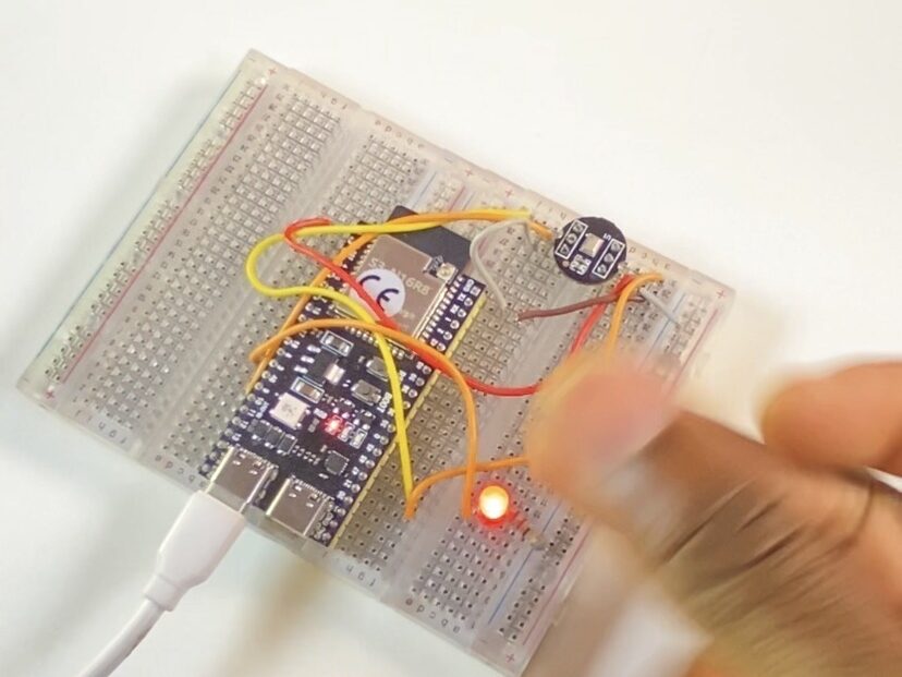
State 2 (ON): When the INMP441 picks up a sharp sound peak—like a clap or snap—the ESP32-S3 instantly toggles the output pin HIGH, turning the red LED on until the next sound peak is detected.