Autres Cours
Interface MFRC522 RFID with ESP32 Board(Arduino IDE)
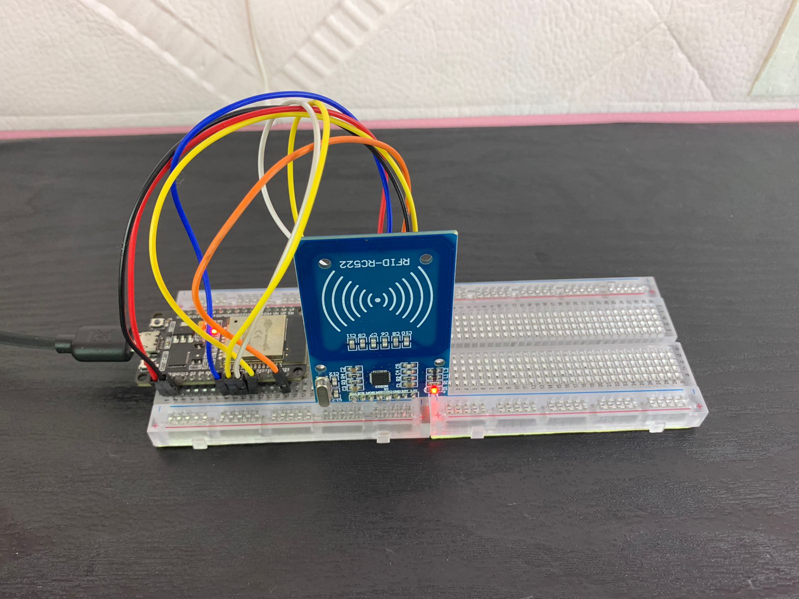
In this tutorial, we are going to learn how to interface the RC522 RFID reader module with the ESP32. You'll learn how to retrieve the UID of RFID cards, and at the end, we'll control two LEDs using RFID.
MFRC522 Reader or Writer
RFID stands for Radio-Frequency Identification. It transmits data that is modulated by an RFID tag. RFID technology, like the one we are using, uses electromagnetic fields to transmit data over short distances. It can be used to identify objects and people, and even to make payments. Nowadays, many businesses use RFID tags on their products for identification and tracking purposes.
An RFID system mainly consists of two components: the reader, which sends and receives signals, and the tag, which stores the data and responds to the reader's queries.
Tags have a proximity integrated circuit that is attached to the object (in our case, cards) to be identified.
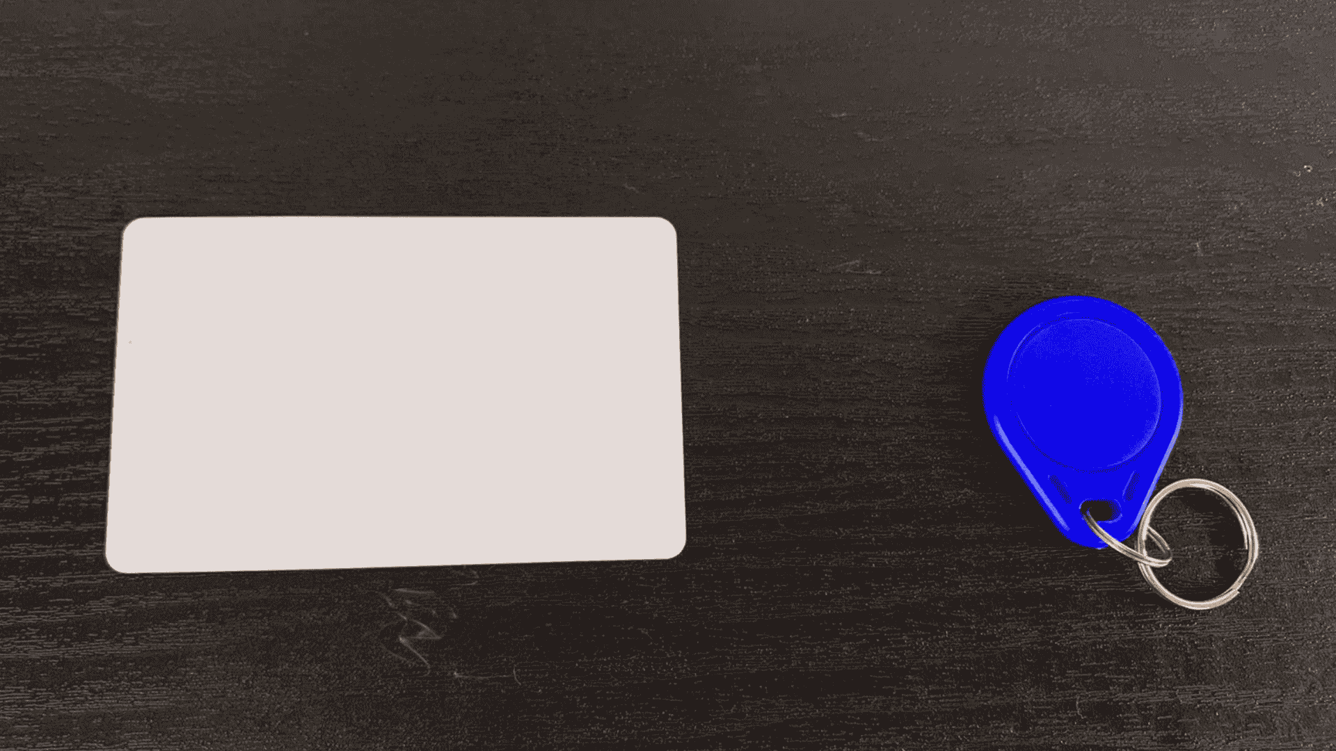
Our MFRC522 RFID module comes with two electromagnetic tag cards for testing. Each card has a unique identification number, called a UID.
The MFRC522 Reader/Writer is a Proximity Coupling Device (PCD) that communicates with RFID tags by sending electromagnetic signals and reading their responses. It acts as a two-way radio frequency transmitter and receiver.
MFRC522 Specifications
- Operating Voltage: 2.5V~3.3V
- Operating/Standby current: 13~26mA/10~13mA
- Communication Protocols: I2C and SPI and UART
- Operating Frequency: 13.56MHz.
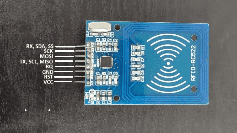
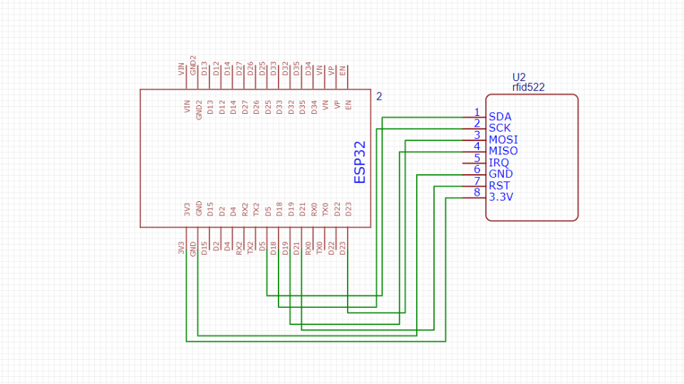
RC522 RFID Pinout
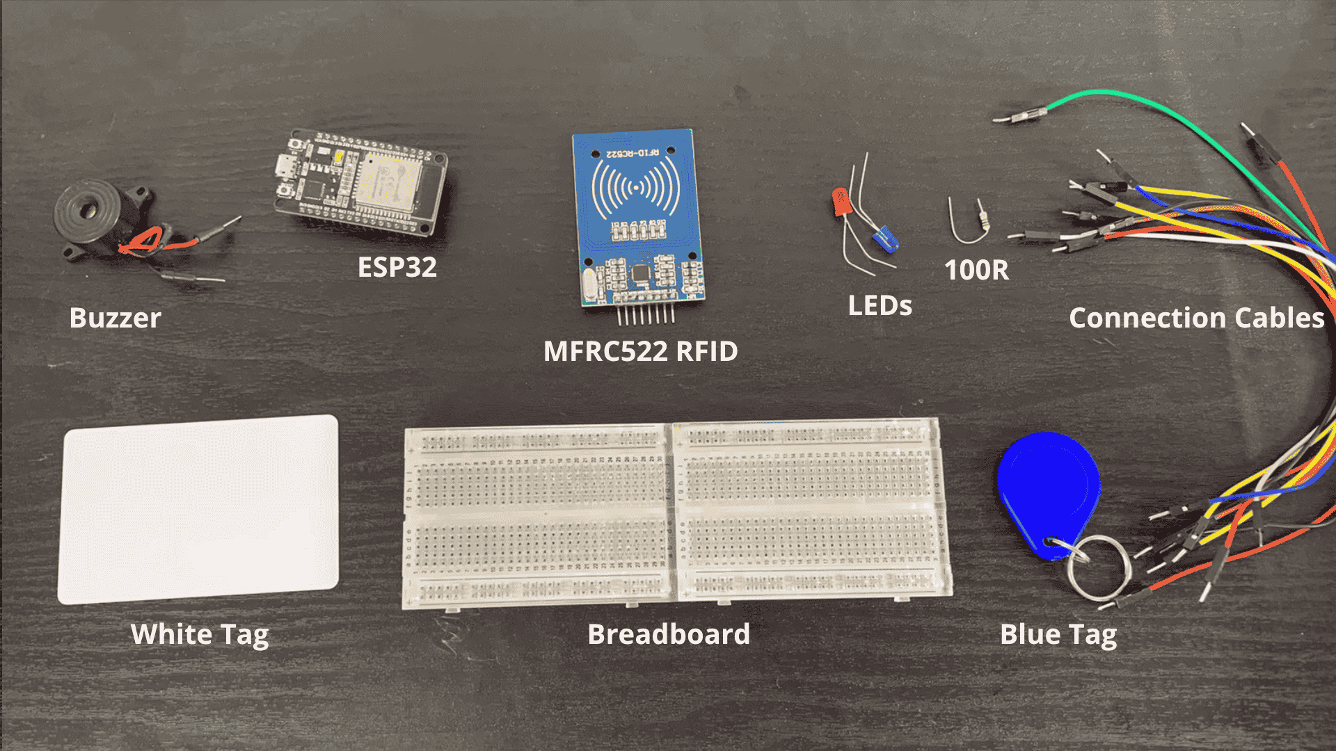
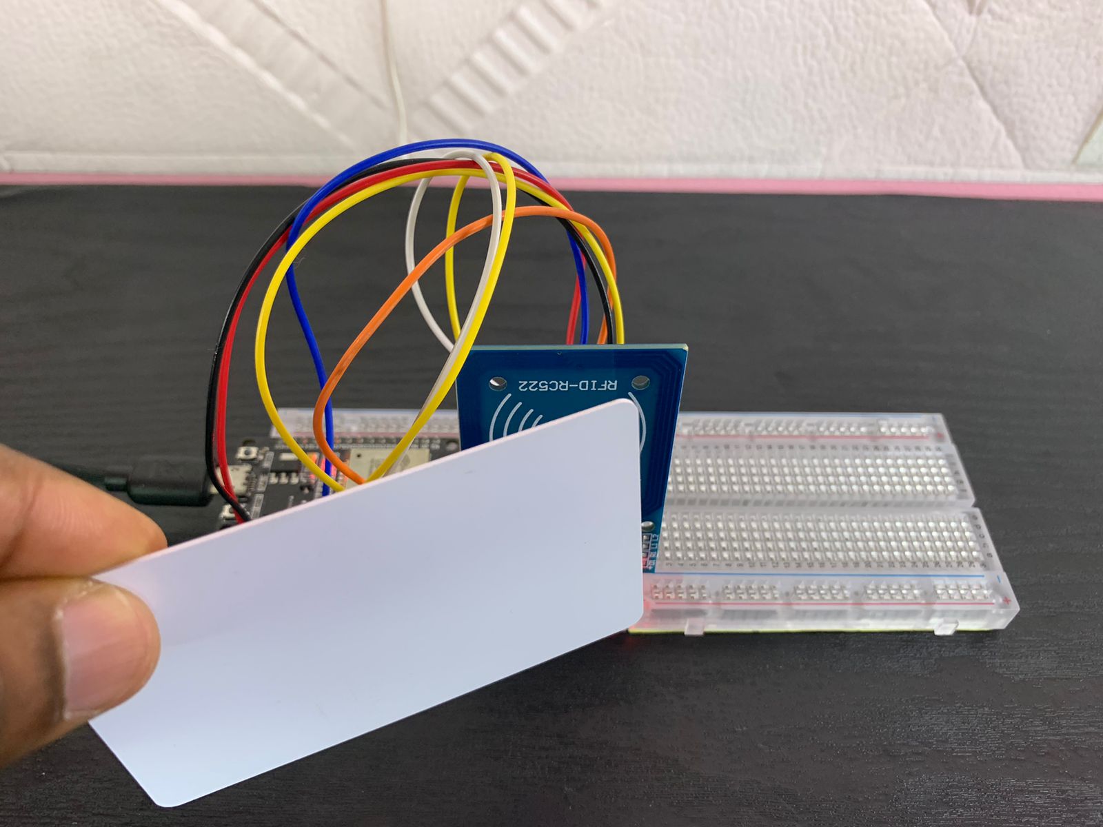
Parts Required
- ESP32
- MFRC522 RFID
- Tags
- 100Ohm Resistor
- Blue LED
- Red LED
- Breadboard
- Jumper wires
Circuit Diagram
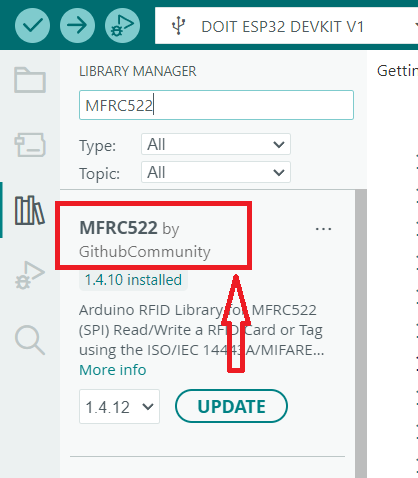
Library Installation on Arduino IDE
In this tutorial, we are going to install the MFRC522 library to control the MFRC522 Reader/Writer sensor module. To do this, go to Sketch > Include Library > Manage Libraries... in the Arduino IDE.
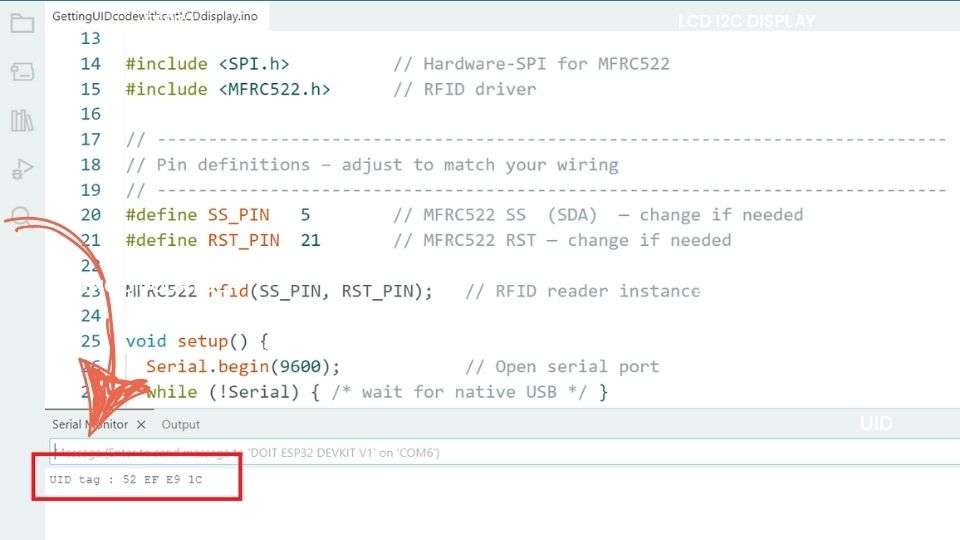
Read RFID Tag UID
The following code reads the raw data (UID) from the blue and white RFID tags. These UIDs can be used later in various RFID-based projects.
#include <SPI.h>                  // Include SPI library for RFID communication
#include <MFRC522.h>              // Include MFRC522 library for RFID
#include <Wire.h>                 // Include Wire library for I2C communication
#include <LiquidCrystal_I2C.h>    // Include LiquidCrystal_I2C library for LCD

// RFID pins
#define SS_PIN 5                 // Define Slave Select pin for RFID
#define RST_PIN 21                // Define Reset pin for RFID

MFRC522 rfid(SS_PIN, RST_PIN);    // Create MFRC522 instance with defined SS and RST pins

// I2C LCD address (typically 0x27 or 0x3F)
LiquidCrystal_I2C lcd(0x27, 16, 2); // Create LCD instance with I2C address 0x27, 16 columns, and 2 rows

void setup() {
  Serial.begin(9600);             // Start serial communication at 9600 baud rate

  // Initialize RFID
  SPI.begin();                    // Initiate SPI bus
  rfid.PCD_Init();                // Initiate MFRC522 RFID module

  // Initialize LCD
  lcd.init();                     // Initialize the LCD
  lcd.backlight();                // Turn on the LCD backlight
  lcd.clear();                    // Clear the LCD screen
  lcd.setCursor(0, 0);            // Set cursor to the first row and column
  lcd.print("Getting UID Tag");   // Display initial message on LCD

  delay(2000);                    // Wait for 2 seconds
  lcd.clear();                    // Clear the LCD screen
}

void loop() {
  // Look for new cards
  if (!rfid.PICC_IsNewCardPresent() || !rfid.PICC_ReadCardSerial()) {
    return;                       // If no new card is present, exit the loop
  }

  // Display UID on Serial Monitor
  Serial.print("UID tag: ");
  String content = "";            // Create a string to hold the UID content
  for (byte i = 0; i < rfid.uid.size; i++) {
    Serial.print(rfid.uid.uidByte[i] < 0x10 ? " 0" : " ");
    Serial.print(rfid.uid.uidByte[i], HEX); // Print each byte of the UID in HEX format
    content.concat(String(rfid.uid.uidByte[i] < 0x10 ? " 0" : " "));
    content.concat(String(rfid.uid.uidByte[i], HEX)); // Append each byte to the content string
  }
  Serial.println();
  Serial.println();

  // Display UID on LCD
  lcd.clear();                    // Clear the LCD screen
  lcd.setCursor(0, 0);            // Set cursor to the first row and column
  lcd.print("RFID UID:");         // Display message on LCD
  lcd.setCursor(0, 1);            // Set cursor to the second row
  lcd.print(content);             // Display the UID content on LCD

  delay(2000);                    // Hold the display for 2 seconds

  // Halt PICC
  rfid.PICC_HaltA();              // Halt the PICC (card)
}
Read UID from White RFID Tag
Getting the data for the white RFID tag
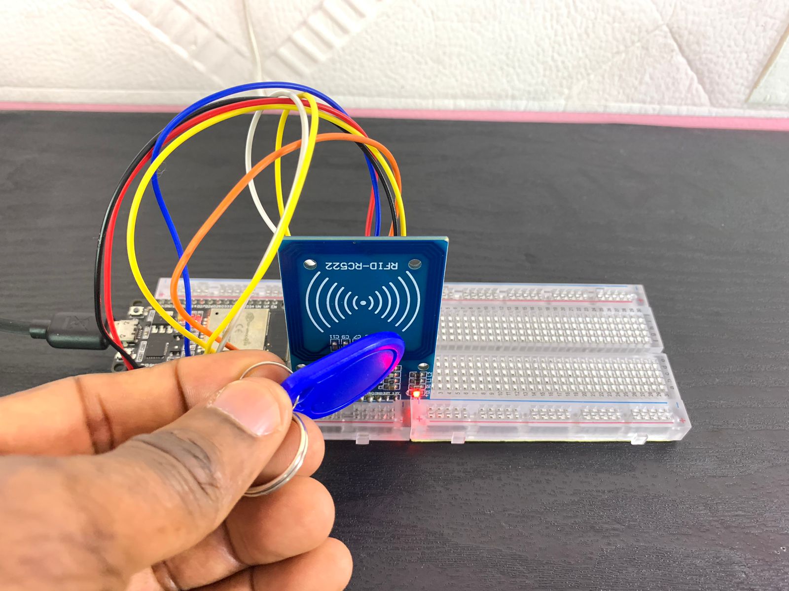
Read UID from Blue RFID Tag
Getting the data for the blue RFID tag
RFID Tag Validation with ESP32 – LED and Buzzer Feedback System
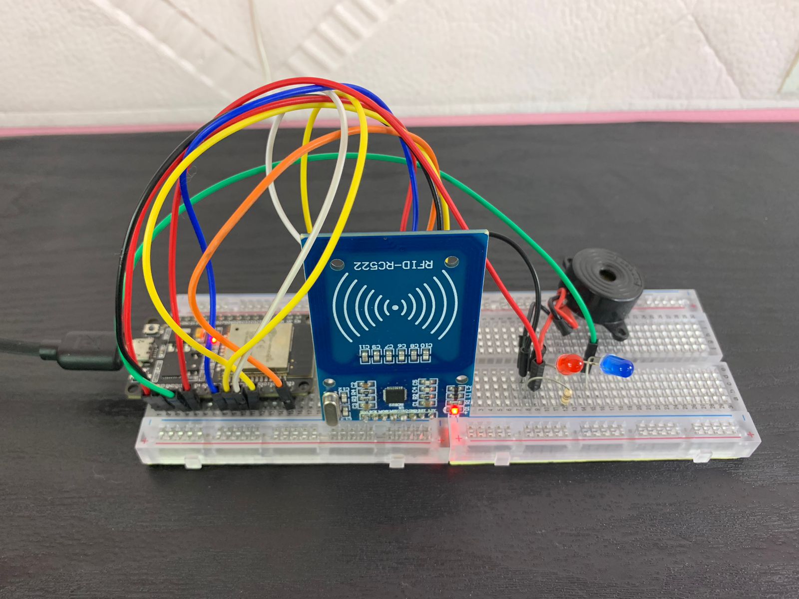
In this example, I'm going to demonstrate how to control two LEDs and one buzzer using the raw data (UIDs) retrieved from two RFID tags (the blue and white tags).
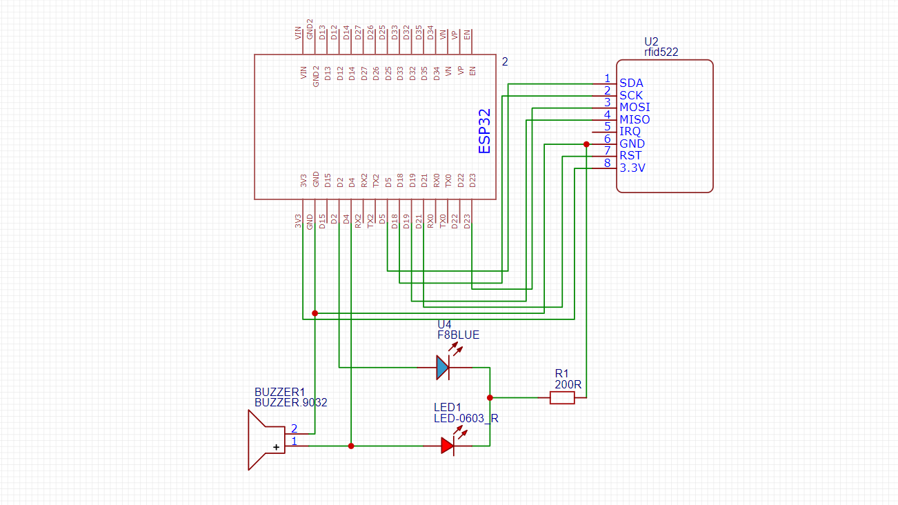
Circuit Diagram
#include <SPI.h> // Include SPI library to enable communication with RFID reader via SPI protocol
#include <MFRC522.h> // Include the MFRC522 library to use the RFID reader functions
#include <Wire.h> // Include Wire library for I2C communication (not used in this sketch but available)
// Define RFID pins
#define SS_PIN 5 // Define Slave Select (SDA) pin for the RFID module, connected to GPIO5 of ESP32
#define RST_PIN 21 // Define Reset pin for the RFID module, connected to GPIO21 of ESP32
// Define LED pins
#define Blue_LED 2 // Define the Blue LED pin (used to indicate authorized access), connected to GPIO2
#define Red_LED 4 // Define the Red LED pin (used to indicate unauthorized access), connected to GPIO4
// Create an instance of the RFID reader with the defined pins
MFRC522 rfid(SS_PIN, RST_PIN);
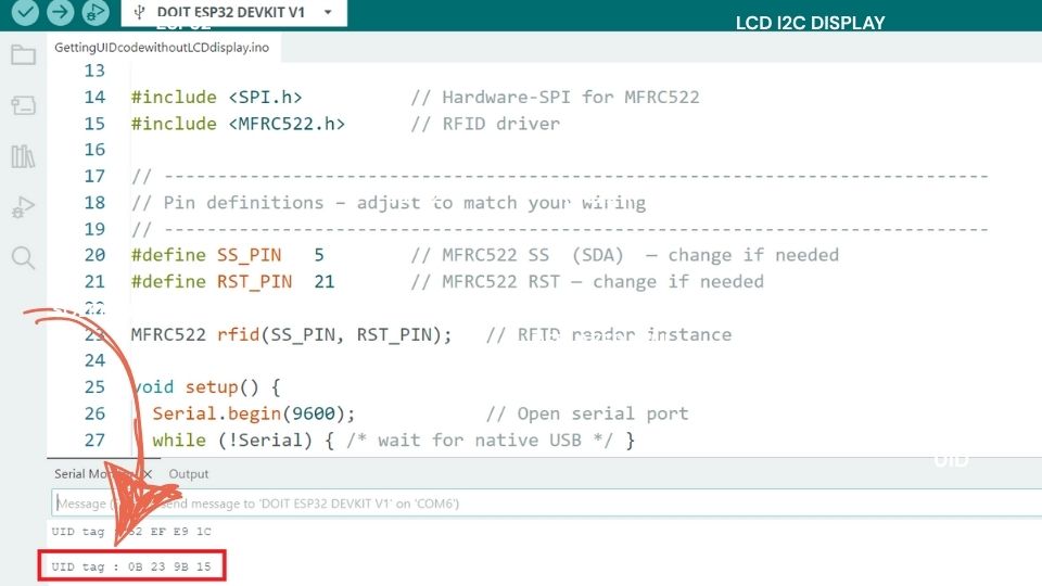
// Store the UID of the authorized RFID card/tag
byte authorizedUID[] = {0x0B, 0x23, 0x9B, 0x15}; // Replace with the UID of your authorized RFID tag/card
void setup() {
Serial.begin(115200); // Initialize serial communication at 115200 baud rate for debugging
pinMode(Blue_LED, OUTPUT); // Set the Blue LED pin as output
pinMode(Red_LED, OUTPUT); // Set the Red LED pin as output
digitalWrite(Blue_LED, LOW); // Make sure the Blue LED is off at startup
digitalWrite(Red_LED, LOW); // Make sure the Red LED is off at startup
SPI.begin(); // Start the SPI bus to communicate with the RFID module
rfid.PCD_Init(); // Initialize the RFID reader module
Serial.println("Place your RFID card near the reader..."); // Print message on Serial Monitor
}
void loop() {
// Check if a new RFID card is present and can be read
if (!rfid.PICC_IsNewCardPresent() || !rfid.PICC_ReadCardSerial()) {
return; // If no card is detected or cannot read card, exit the loop
}
Serial.print("UID tag: "); // Print start of UID message
String content = ""; // Create an empty string to store the UID in text format
// Loop through the bytes of the UID read from the card
for (byte i = 0; i < rfid.uid.size; i++) {
Serial.print(rfid.uid.uidByte[i] < 0x10 ? " 0" : " "); // Print a leading 0 if value is less than 0x10
Serial.print(rfid.uid.uidByte[i], HEX); // Print each byte of UID in hexadecimal format
content.concat(String(rfid.uid.uidByte[i] < 0x10 ? " 0" : " ")); // Add leading space if needed
content.concat(String(rfid.uid.uidByte[i], HEX)); // Concatenate the hex value to the content string
}
Serial.println(); // Print a newline after displaying the full UID
// Check if the scanned UID matches the authorized UID
bool authorized = true; // Assume authorized initially
for (byte i = 0; i < rfid.uid.size; i++) {
if (rfid.uid.uidByte[i] != authorizedUID[i]) { // Compare each byte
authorized = false; // If any byte doesn't match, mark as unauthorized
break; // No need to check further
}
}
if (authorized) {
Serial.println("Access Granted!"); // Print access granted message
digitalWrite(Blue_LED, HIGH); // Turn ON the Blue LED (authorized access)
delay(2000); // Keep the LED ON for 2 seconds
digitalWrite(Blue_LED, LOW); // Turn OFF the Blue LED
} else {
Serial.println("Access Denied!"); // Print access denied message
digitalWrite(Red_LED, HIGH); // Turn ON the Red LED (unauthorized access)
delay(2000); // Keep the LED ON for 2 seconds
digitalWrite(Red_LED, LOW); // Turn OFF the Red LED
}
rfid.PICC_HaltA(); // Halt the current RFID card so it can be read again next time
}How does this project work?
When the MFRC522 reader module detects the wrong tag (white tag), the red LED will turn on for 2 seconds, and the buzzer will sound for 2 seconds as well. However, when the correct tag (blue tag) is detected, the blue LED will turn on for 2 seconds.
Testing the project
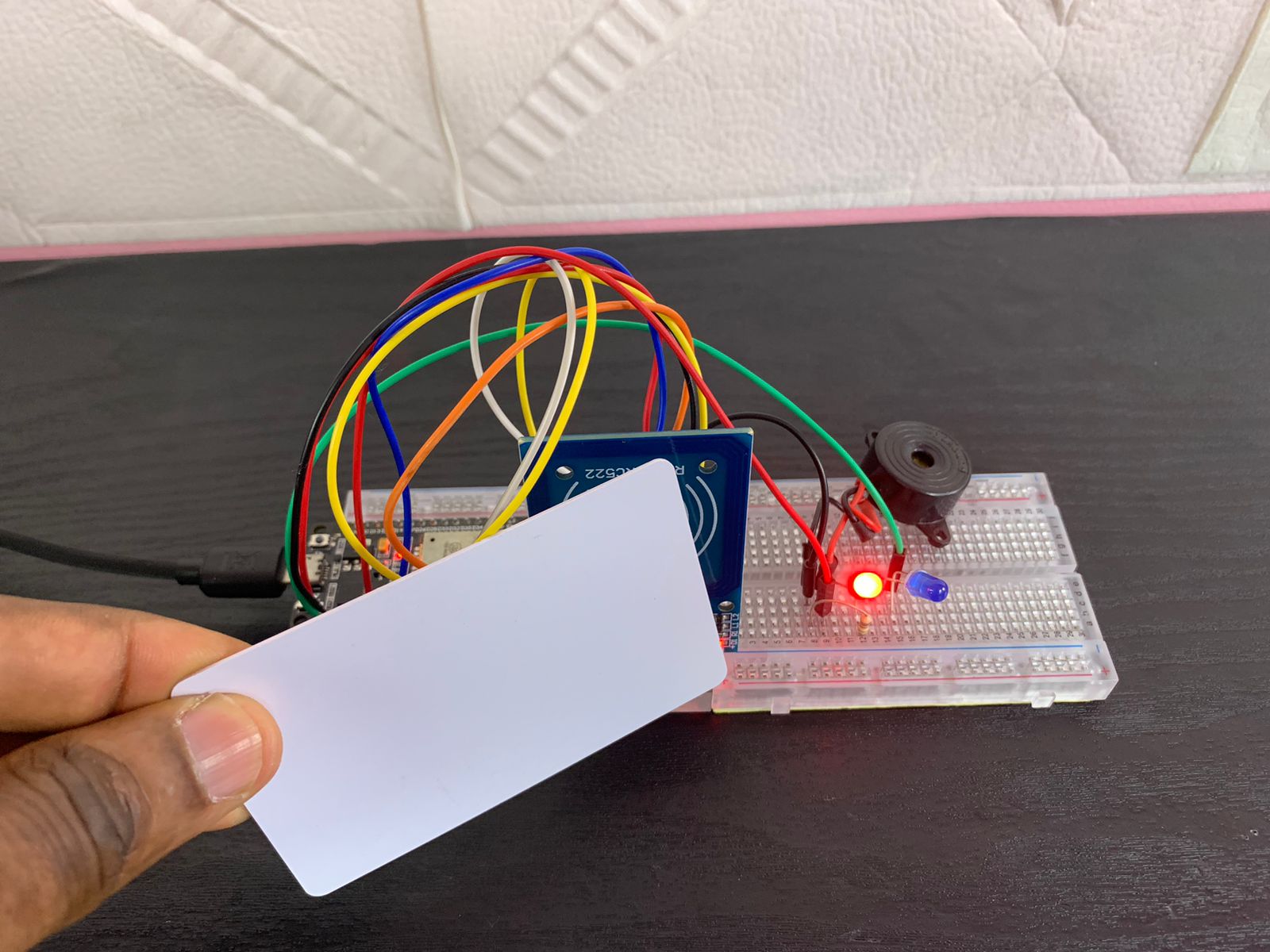
Detecting the wrong Tag
When the MFRC522 reader module detects the wrong tag (white tag), the red LED will turn on for 2 seconds, and the buzzer will sound for 2 seconds.
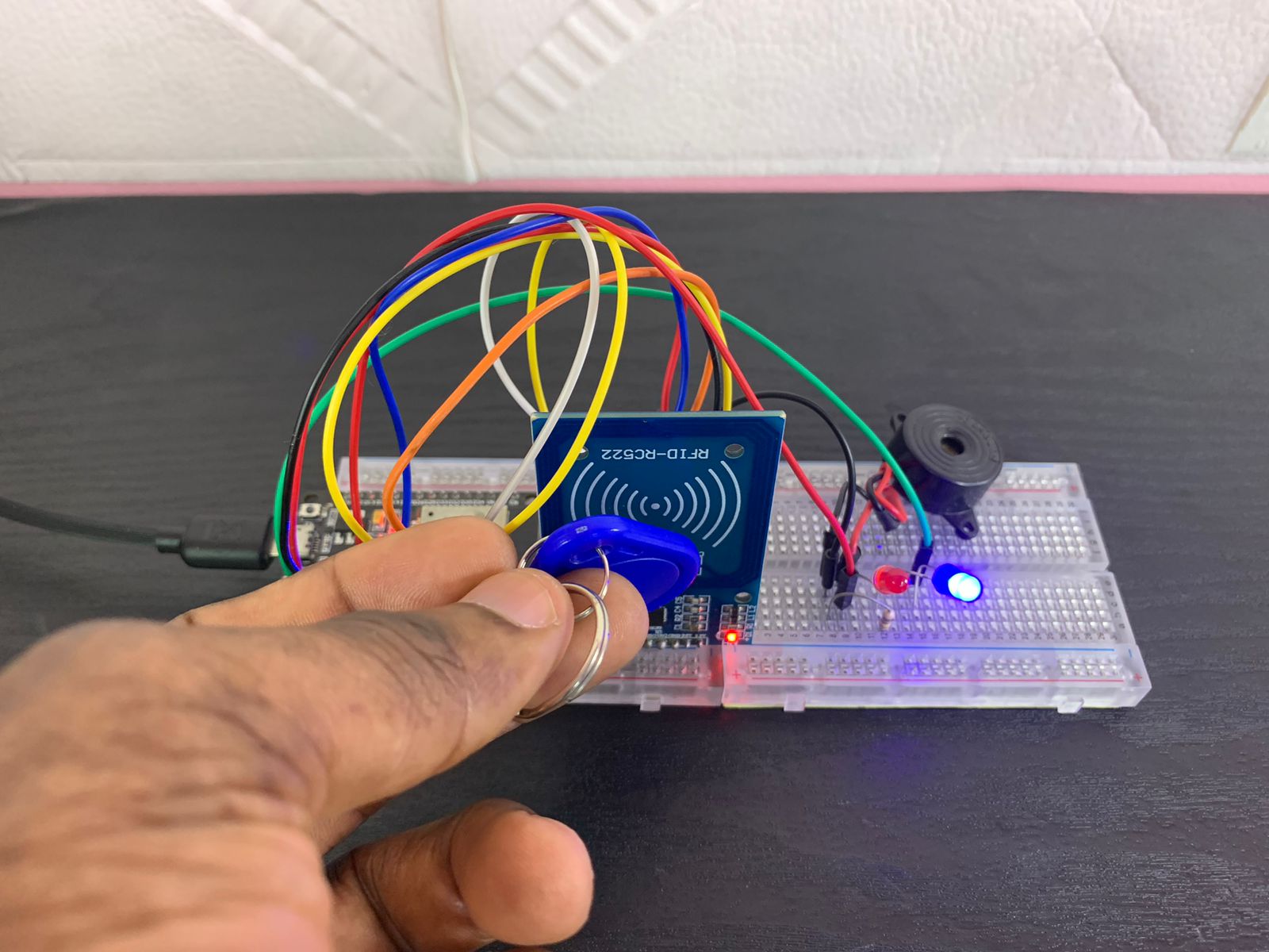
Detecting the good Tag
When the correct tag (blue tag) is detected, the blue LED will turn on for 2 seconds.
Application
- Access Control for Offices and Homes
- School and University Attendance System
- Employee Time Tracking in Companies
- Inventory and Asset Management
- Library Book Checkout System
- Tool Locker Authorization in Workshops
- Medical Equipment Validation in Hospitals
Produits Recommandés
No products are available